Operating Instructions_VF335_en.pdf - 第472页
9|Spare and wear parts 9.4 Positioning systems 9.4.1 Single pot positioning system (single track) Overview Fig.200: EM113-20-00 Ersa GmbH Operating Instructions_VF335_en|Rev. 14|30/11/2017 472/695
9|Spare and wear parts
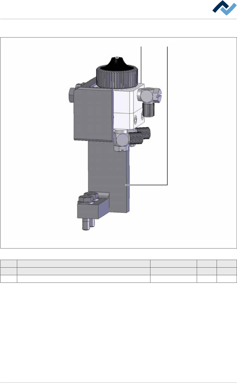
9.3.8 Area-Spray head (Option)
1 2
Fig.199: EM113-41-09-00a
Pos Description Item number A B
1 "Schütze" type area spray head, round shape, 0,2 269741 x
2 Holder for area-spray head "Schütze" 276596 x
Ersa GmbH Operating Instructions_VF335_en|Rev. 14|30/11/2017 471/695
9|Spare and wear parts
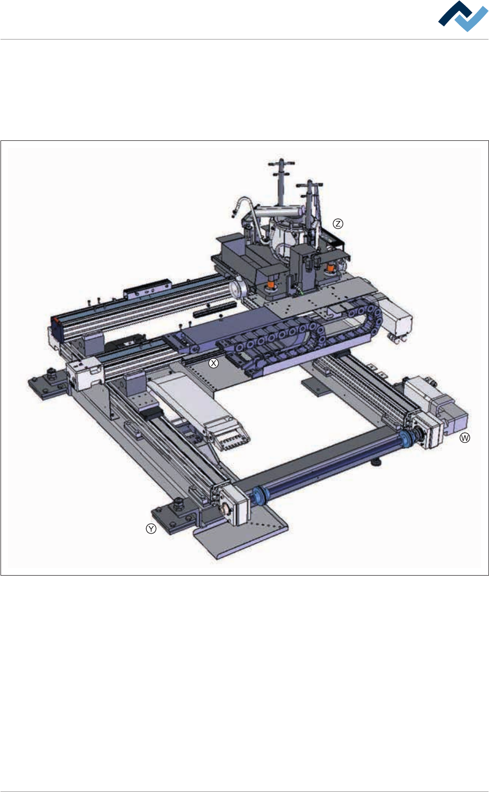
9.4 Positioning systems
9.4.1 Single pot positioning system (single track)
Overview
Fig.200: EM113-20-00
Ersa GmbH Operating Instructions_VF335_en|Rev. 14|30/11/2017 472/695
9|Spare and wear parts
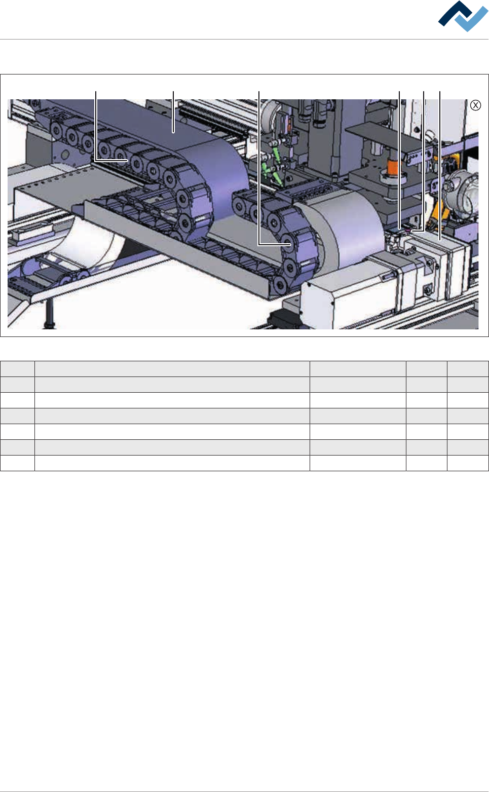
Single solder pot positioning system, view [X]
1 1 52 3 4
Fig.201: EM113-20-00Aa
Pos Description Item number A B
1 Energy chain 152270 x
2 Energy chain 174537 x
3 Steel band 38 mm x 1167 mm 175813 x
4 Tooth belt 25AT10HPF; 2440 mm 216456 x
5 Wearing part package steel band deflection 175815 x
6 Blanket for positioning system: EM113-20-00A (not shown) 253569 x
Ersa GmbH Operating Instructions_VF335_en|Rev. 14|30/11/2017 473/695