Operating Instructions_VF335_en.pdf - 第331页
8|Service and maintenance ü Check and adjust the nitrogen input pressure a) Visual inspection of the pressure reducer. For each soldering unit, a pressure reducer is available. b) Read the current pressure on the press…
8|Service and maintenance
8.6.8 Solder level monitoring Checking input pressure
1
2
31
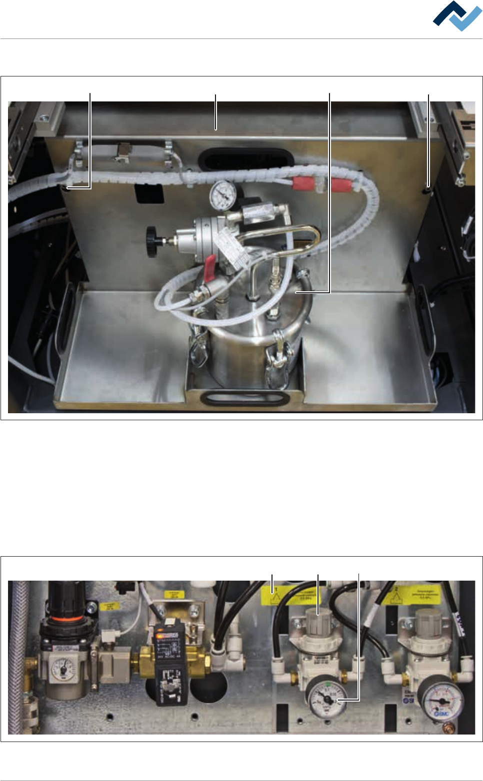
Fig.104: Disassembling the covering plate
ü To disassemble the covering plate:
a) Open the door in the fluxer area.
b) Loosen the screws (1).
c) Lift the covering plate (2) and remove it from the machine together with the
storage tank.
d) Place the covering plate on a level surface.
ð The compressed air and nitrogen supply unit becomes visible.
123
Fig.105: Solder level monitoring Adjusting input pressure
Ersa GmbH Operating Instructions_VF335_en|Rev. 14|30/11/2017 330/695

8|Service and maintenance
ü Check and adjust the nitrogen input pressure
a) Visual inspection of the pressure reducer. For each soldering unit, a pressure
reducer is available.
b) Read the current pressure on the pressure gauge (1) and compare it with the
data on the label (3).
ð If pressure has been set too low:
c) Remove the adjusting knob (2) pulling it upwards and change the pressure by
turning the adjusting knob until the correct pressure is displayed.
d) Press the adjusting knob down again.
ð The process has now been completed.
Ersa GmbH Operating Instructions_VF335_en|Rev. 14|30/11/2017 331/695
8|Service and maintenance
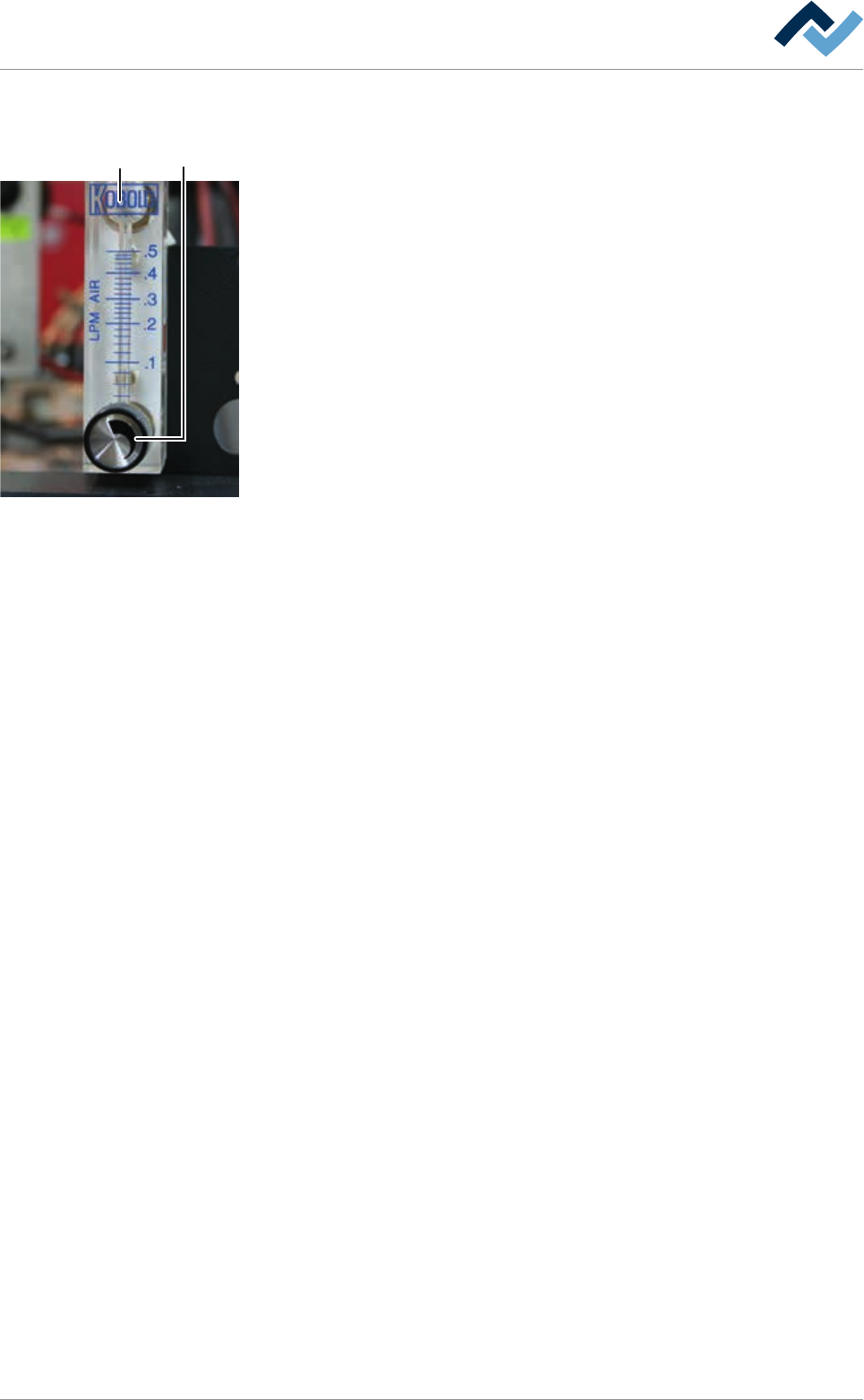
8.6.9 Checking the nitrogen flow to the solder level monitoring
12
Checking and setting the nitrogen flow
ü To check the nitrogen flow for monitoring the solder level:
a) For each soldering module, a flow meter is available. The flowmeters (2) are
located above the soldering modules on the right side, behind the cover plate.
b) On the adjustment knob (1), set a value of at least 0.15 l/min.
c) Repeat the procedure with all available flow meters.
ð The process has now been completed.
Ersa GmbH Operating Instructions_VF335_en|Rev. 14|30/11/2017 332/695