Operating Instructions_VF335_en.pdf - 第28页
2|Technical data 2.2.2 Bottom pre-heater, dynamic emitter cartridge with glass plate Description Type of heating Dynamic emitter cartridge Rated power (kW) at 400V 12 ( = 8 x 1.5) Dimensions of the emitter cartridge L …
2|Technical data
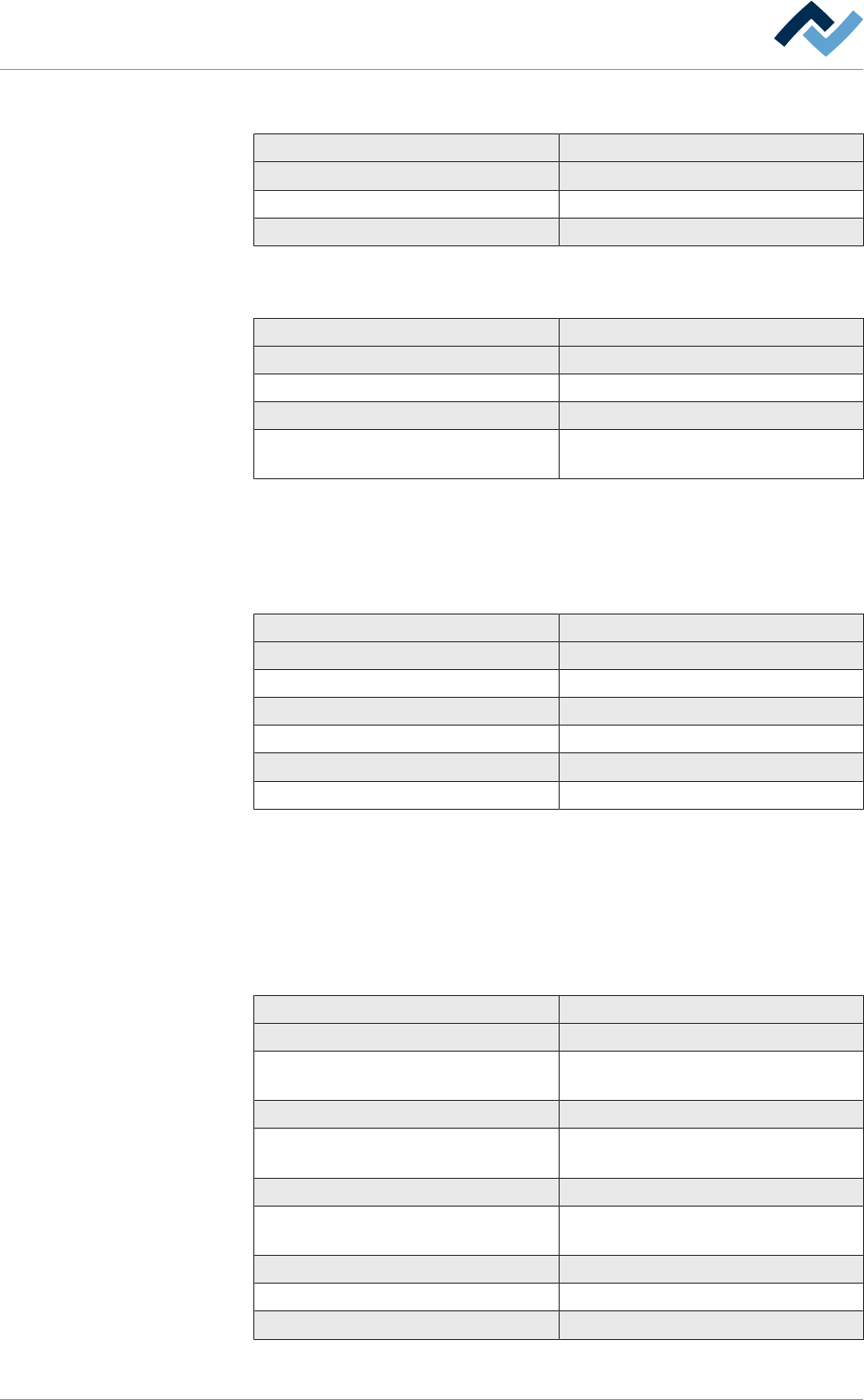
2.1.5 Ambient conditions
Description
Ambient temperature (°C) 10…35
Air humidity (%, non-condensing) 20…95
Continuous noise level (dB A) < 60
2.1.6 Safety devices
Designation
Main switch Lockable
Emergency STOP pushbutton (pieces) 3
Exhaust air duct monitoring With differential pressure switch
Hood Release via hardware / software safety
switch
2.1.7 Electrical data of the entire system
2.1.7.1 Connection data*
Description
Mains voltage 5-wire system N/PE (V) 3 x 230 V / 400 V
Voltage tolerance (%) ± 10
Mains frequency (Hz) 50 / 60
Pre-fuse (A, delayed action)* 3 x 125
Power consumption (kW)* 34
Nominal current consumption (A)* 60.5
*Depending on the respective development stage. The actual values are specified
on the type plate of your soldering system.
2.2 Technical data of the single units
2.2.1 Spray fluxer
Designation
Flux material stock 2
Flux material type according to IEC
61190-1-1*
RO, RE, OR
Flux material effectiveness level L0, L1, M0
Spray nozzle (µm), alternative sizes avail-
able on request
130
Spray pressure (bar) 0.5…1
Spray application width with 130 µm
spray nozzle (mm)
2…8
Flux material speed (mm/sec) 20
Positioning speed (mm/sec) 400
Positioning accuracy (mm) ± 0.2
*The materials used in the fluxer unit are approved for the above-mentioned flux.
Ersa GmbH Operating Instructions_VF335_en|Rev. 14|30/11/2017 27/695

2|Technical data
2.2.2 Bottom pre-heater, dynamic emitter cartridge with glass plate
Description
Type of heating Dynamic emitter cartridge
Rated power (kW) at 400V 12 ( = 8 x 1.5)
Dimensions of the emitter cartridge L x
W (mm)
500 x 765
Maximum PCB size L x W (mm) 508 x 508
* Depending on the development stage, several preheaters can be installed.
2.2.3 Top pre-heating, compressed air heater (option)
Description
Type of heating Medium wave emitters, convection
Rated power (kW) at 230V 4 ( = 2 x 2.0)
Dimensions of the radiator cassette L x
W (mm)
665 x 400
Pneumatics stand-by pressure (MPa) 0.03
Pneumatics working pressure (MPa) 0.3
Ersa GmbH Operating Instructions_VF335_en|Rev. 14|30/11/2017 28/695
2|Technical data
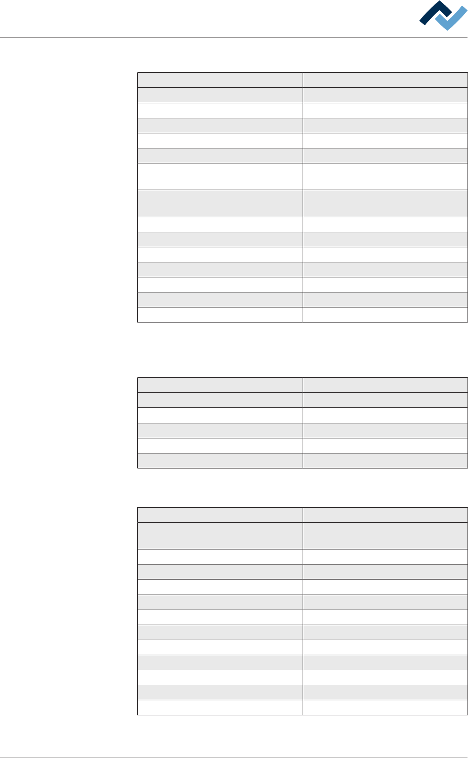
2.2.4 Point and path soldering module
Description
Module type Point and path soldering module
Heating output (kW) 1.15
Solder content approx. (Kg) 13
Heat-up time to 280°C (h) 1.25
Maximum solder temperature (°C) 330
Minimum inside diameter of the solder
nozzle (mm)
3
Smallest outer diameter of the solder
nozzle (mm)
6
Maximum solder wave height (mm) 5
Minimum side clearance (mm) 3
Soldering speed X/Y axis (mm/sec) 10
X/Y axis positioning speed (mm/sec) 0.5…200
Positioning speed Z axis (mm/sec) 0.5…100
Positioning accuracy (mm) ± 0.15
Handling system 3-axis system with servo drives
Depending on the development stage, several soldering modules can be installed.
2.2.5 Solder feeding: Point and path soldering module
Description
Type of solder lead Solder wire
Maximum wire diameter (mm) 2
Maximum coil diameter (mm) 125
Maximum coil height (mm) 125
Maximum roller weight (Kg) 4
2.2.6 DIP soldering unit with impeller pump
Designation
Unit type DIP soldering unit with impeller pump,
motor-driven
Heating power (kW) 10.2
Solder content approx. (kg)
Heat up time to 280°C (min)
Maximum solder temperature (°C) 300
Maximum solder wave height (mm)
Minimum edge clearance (mm)
Maximum board length (mm)
Maximum board width (mm)
Z-axis positioning speed (mm/sec)
Positioning accuracy (mm) ± 0.25
Handling system Motorized with tooth belt drive
Ersa GmbH Operating Instructions_VF335_en|Rev. 14|30/11/2017 29/695