Operating Instructions_VF335_en.pdf - 第197页
6|Function description 6.9.12.3 Soldering module data set (double pot) In this variant, two pots are located on the axis system. In addition, in the table of coordinates, the [Tool] register appears again if both pots …
6|Function description
Example of use
Soldering program editor
Set data
Set data
Flux unit Soldering unit 1
Set
Hide
Description
Endposition X [mm]
Endposition Y [mm]
Speed X/Y [mm/s]
mode
Spray amount [%]
Spray time [s]
Z while moving [mm]
Endposition X [mm]
Endposition Y [mm]
Speed X/Y [mm/s]
Endposition Z [mm]
Speed Z [mm/s]
Wave height [%]
Soldering time [s]
Lower value [%]
Lowering time [s]
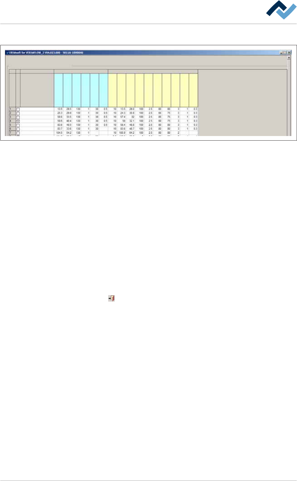
– Set number 1: Position [X = 13.5] / [Y = 29.0] is approached with the [Speed X/Y
[mm/s]] of 100 mm/s. In the process, the distance to the [Z while moving
[mm]] PCBs is 10 mm. The nozzle is then lifted to the [Endposition Z
[mm]Speed Z [mm/s]] = 80 mm/s and solders a spot with the [wave height
80%] for the [Soldering time [s]] of 3 seconds. Within the [Lowering time [s]] of
0.3 seconds, the height of the solder wave is reduced by the [Lower value [%]]
of 1%.
– Set number 4: This data set is hidden (the [Hide] checkbox is enabled). The
data set is therefore not processed.
– Sets number 7 and 8: Position [X = 105.9] / [Y = 64.2] is approached with the
[Speed X/Y [mm/s]] of 100 mm/s. In the process, the distance to the [Z while
moving [mm]] PCBs is 10 mm. The nozzle is then lifted on the [Endposition Z
[mm]] = 2.5 mm with the [Speed Z [mm/s]] = 50 mm/s, and solders a point with
the [wave height 80%] for the [Soldering time] of 2 seconds. The solder wave is
not lowered. Now, set number 8 is processed, the solder nozzle remains in the
position [Z while moving [mm]] = 2.5 mm. Position [X = 105.9] / [Y = 53.8] is ap-
proached with the [Speed X/Y [mm/s]] of 100 mm/s. During that process, a
path is soldered. Within the [Lowering time [s]] of 0.3 seconds, the height of
the solder wave is reduced by the [Lower value [%]] of 1%.
Click on
to close the dialog.
Ersa GmbH Operating Instructions_VF335_en|Rev. 14|30/11/2017 196/695
6|Function description
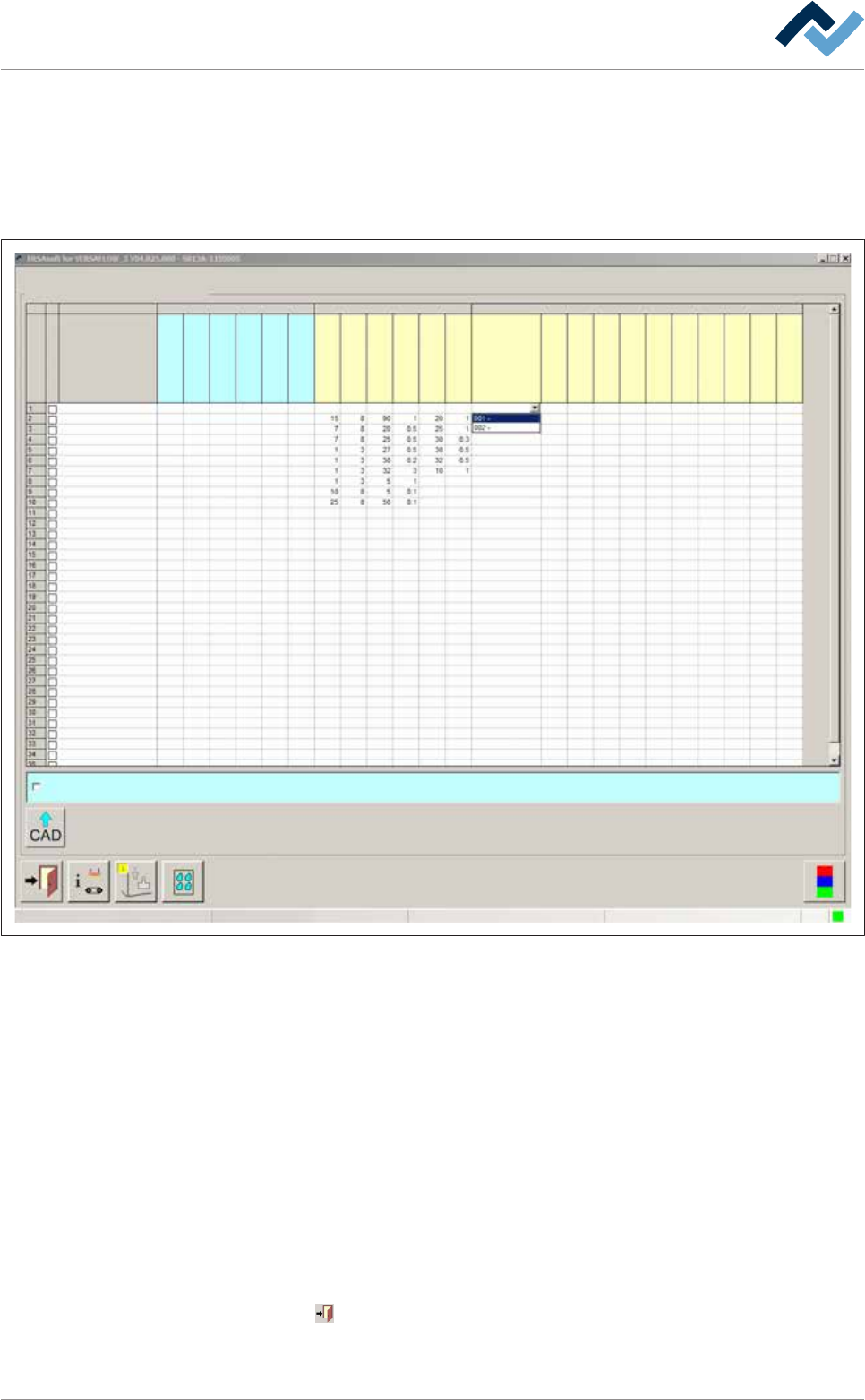
6.9.12.3 Soldering module data set (double pot)
In this variant, two pots are located on the axis system. In addition, in the table of
coordinates, the [Tool] register appears again if both pots have been enabled in the
[General soldering program data] dialog.
Please observe the following picture:
Set data
Set dataSoldering program editor
Fluxer coordinates relate to nozzle 1
user: Service Maintenance mode
Set
Hide
Description
Endposition X [mm]
Endposition Y [mm]
Speed X/Y [mm/s]
mode
Spray amount [%]
Spray time [s]
Flux unit Soldering unit 1 Soldering unit 2
Solder pot 1
Solder pot 2
Endposition Z [mm]
Speed Z [mm/s]
Wave height [%]
Soldering time [s]
Lower value
Lowering time [s]
Tool
Z while moving [mm]
Endposition X [mm]
Endposition Y [mm]
Speed X/Y [mm/s]
Endposition Z [mm]
Speed Z [mm/s]
Wave height [%]
Soldering time [s]
Lower value
Lowering time [s]
Fig.45: Data sets: Soldering module 2 has two solder pots in this example.
Entering target coordinates
ü To enter target coordinates in case of a double pot:
a) In the [General soldering program data] dialog, enable both pots and then
open the [Set data] dialog.
b) Enter target coordinates and parameters in the table. With regard to this,
please read the Soldering module data set (single pot) [
}194] chapter.
ð An additional [Tool] register appears now in the table.
c) Click on a cell in the [Tool] register.
ð A dropdown menu appears in the cell.
d) Select the pot to be used for soldering in the dropdown menu.
ð The process has now been completed.
Click on
to close the dialog.
Also see
Ersa GmbH Operating Instructions_VF335_en|Rev. 14|30/11/2017 197/695