Operating Instructions_VF335_en.pdf - 第430页
8|Service and maintenance ð The solder pot is now moved out of the machine and will automatically stop in its final position. l) Release the buttons (14). 17 16 18 19 21 22 23 24 25 25 26 20 Fig.167: Loosen all quick-…
8|Service and maintenance
10 9
10 1112 13
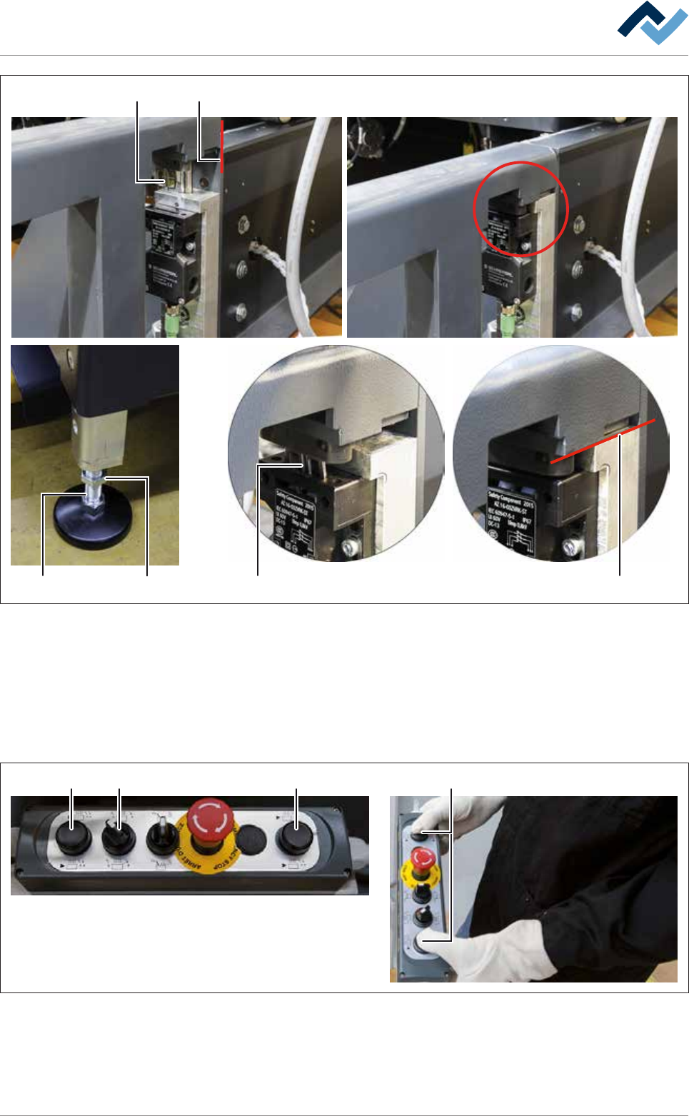
Fig.165: Lowering the replacement rack and inserting the switching cams
i) Using the lifting cart, carefully lower the replacement rack until its guide rails
are placed level on both locating surfaces of the machine (11).
ð At this point, the adjustable feet (12) of the replacement rack must be on
the floor.
ð While the equipment is lowered, the switching cams (10) must slide into
the switch and must not be canted.
1514 14 14
9
Fig.166: Remove the DIP solder pot
j) On the control console, rotate switch (15) in the position shown.
k) Press and hold both buttons at the same time (14).
Ersa GmbH Operating Instructions_VF335_en|Rev. 14|30/11/2017 429/695
8|Service and maintenance
ð The solder pot is now moved out of the machine and will automatically
stop in its final position.
l) Release the buttons (14).
17 16
18 19 21 22 23 24
25 2526
20
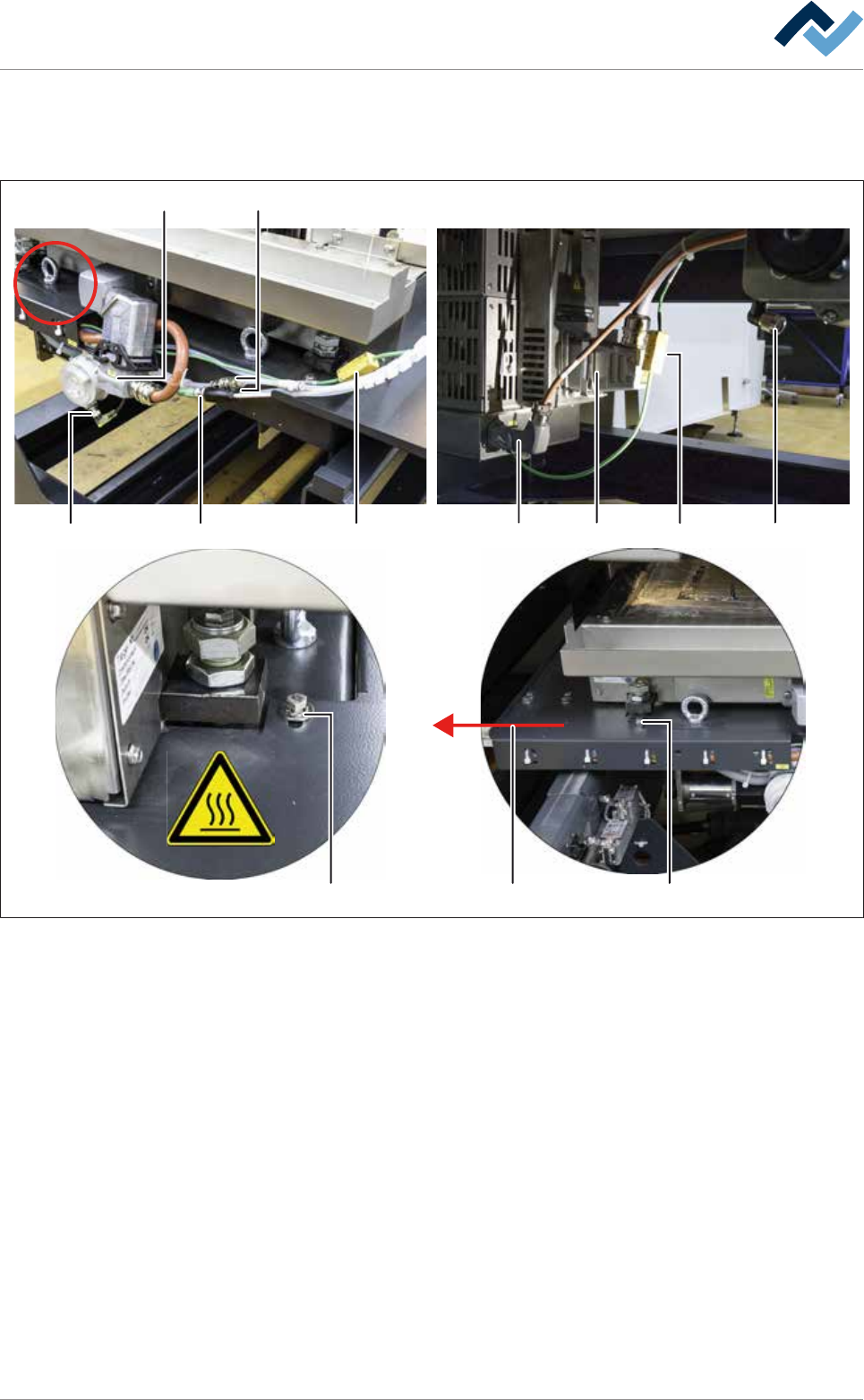
Fig.167: Loosen all quick-acting couplings and plug-in connectors
m)Loosen both quick-acting couplings (16).
n) Loosen all eight plug-in connectors (17-24).
o) Loosen both screws (25) of the holder of the cable carrier on the front and on
the rear of the DIP solder pot.
p) Pull the holder of the cable carrier (26) to the left, lift it over the solder pot and
place it forwards in the machine.
q) Secure the solder pot to the replacement rack using the fixing bar.
r) Using the lifting cart, lift the replacement rack until the height (2) is at least 15
mm greater than the height (1) of the DIP soldering module guide rail.
s) Carefully pull the lifting cart away from the machine.
t) Store the replacement rack with the DIP solder pot in a suitable location.
u) Shut off the area around the DIP solder pot with a red and white safety chain
and a warning sign.
Ersa GmbH Operating Instructions_VF335_en|Rev. 14|30/11/2017 430/695
8|Service and maintenance
v) If necessary, connect the removed DIP solder pot to the optional heating sta-
tion. With regard to this, also read Chapter Connecting the cold solder pot to
the (optional) heating station and preheating it [}425].
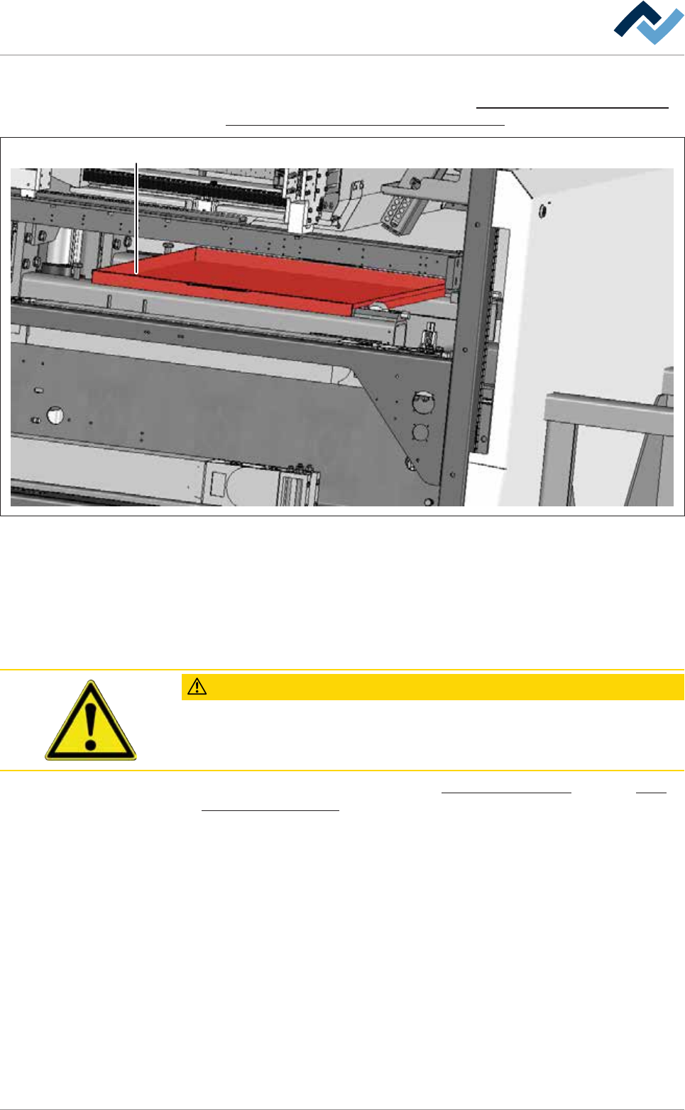
27
Fig.168: Enclosure (27) for cleaning the gassing frame of the DIP soldering module.
w) Push the enclosure (27) under the DIP soldering module.
x) On the machine, clean the gassing frame of the DIP soldering module. Remove
all solder residues.
y) Then remove the enclosure (27) from the DIP soldering module.
ð The process has now been completed.
CAUTION
Contamination of the solder alloy due to solder residues!
Carefully remove all solder residues of the alloy of the removed DIP solder pot in or-
der to avoid any contamination of the new DIP solder pot.
With regard to this, please read Chapters Cleaning agents used [}300] and Tools
and auxiliary materials [}301].
Ersa GmbH Operating Instructions_VF335_en|Rev. 14|30/11/2017 431/695