Operating Instructions_VF335_en.pdf - 第185页
6|Function description 6.9.11 Working with deflection measurement If your machine is equipped with deflection measurement, you can use this func- tion to automatically compensate for the printed circuit board deflectio…
6|Function description
6.9.10 Settings of the Versaeye inspection system (option)
If the Versaeye inspection system must be used in the soldering program, it must
be configured in the machine control.
With regard to this, please also read the Versaeye inspection system (option)
[}269]chapter.
In order to use the Versaeye inspection system in the soldering program, the Exit
unit must be enabled in the soldering program.
Activate the [Exit unit] in the soldering program
ü Activate the [Exit unit] in the soldering program:
a) In the [General soldering program data] dialog, enable the module checkbox at
level 1.
ð The [Exit unit] module is now enabled and can be used in the soldering pro-
gram.
Setting the conveyor speed
ü To set the conveyor speed:
a) In the [General soldering program data] dialog in level 3, click on the input field
of the conveyor section.
b) Enter the conveyor speed in [%] of the maximum possible speed value.
ð This is the speed at which the board is conveyed into the next module.
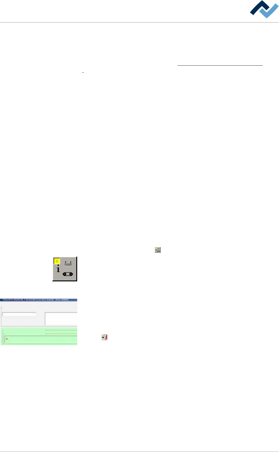
Performing extended settings in the [General additional data] dialog
ü To perform extended settings:
a) Open the [General soldering program data] dialog.
b) Below Level 6, click on the
button in the corresponding module.
Open the [General additional data] dialog. The yellow square indicates how often
the dialog has already been opened.
Activate Versaeye in the soldering program
Version:
user: none Maintenance mode
Active
General additional data
Program informations
Soldering program
editor
General additional data
Inspektionssystem
Last modification by:
Program name:
Exit unit
versaEye
ersa
0020
Infotext:
Conveyor
Graphical
data
Conveyor width adjustment mm380.0
Process time
ü Activate the Versaeye inspection system in the soldering program:
a) In the [Inspection system] dialog, enable the [Active] checkbox.
ð The Versaeye inspection system is now enabled and can be used in the solder-
ing program.
Click on
to close the dialog.
Ersa GmbH Operating Instructions_VF335_en|Rev. 14|30/11/2017 184/695

6|Function description
6.9.11 Working with deflection measurement
If your machine is equipped with deflection measurement, you can use this func-
tion to automatically compensate for the printed circuit board deflection. A sensor
reads the height [Z] in two pcb points. The controller uses said readings to calculate
the deflection and correct distances accordingly.
ü To set reference positions:
a) Enter a Reference position [X] and [Y] each time. The pcb should not deflect in
this position, and no component should be positioned on the lower side of the
pcb. This position should preferably be on the pcb edge.
b) Enter a Measuring position [X] and [Y] each time. In this position the pcb
should be deflecting at the most, no component should be positioned on the
lower side of the pcb.
c) Enable the [Use] checkbox.
ð Only the controller takes into account the pcb deflection. Before the actual sol-
dering process, the sensor compares the [Reference position] with the [Meas-
uring position] and determines the deflection. In this ways the machine cycle
time can be extended.
Click on
to close the dialog.
Ersa GmbH Operating Instructions_VF335_en|Rev. 14|30/11/2017 185/695
6|Function description
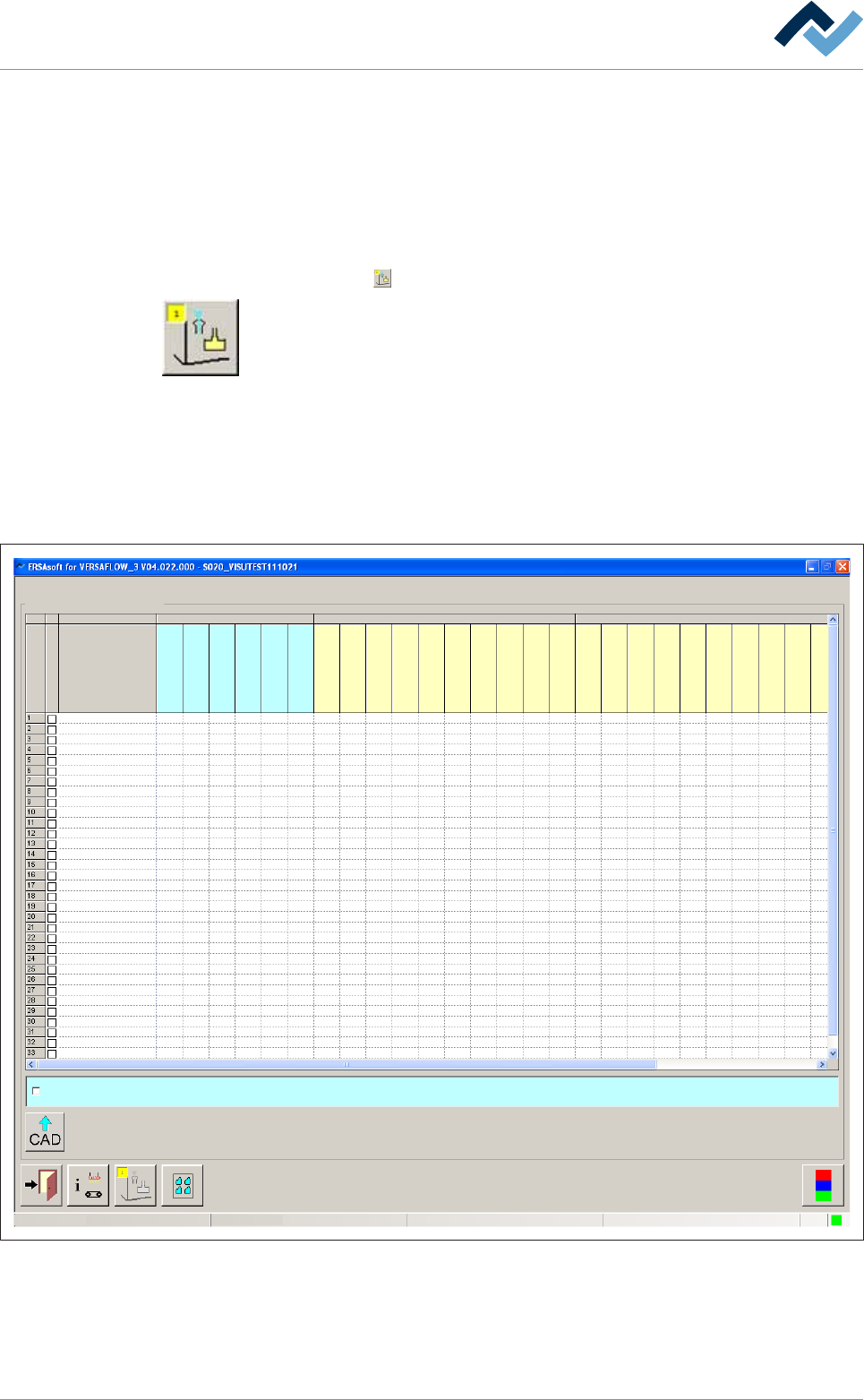
6.9.12 Working with data sets
The [Set data] dialog contains all the necessary data for the manufacturing process.
Creating data sets in the [Set data] dialog
ü To create data sets:
a) Open the [General soldering program data] dialog.
b) Click on the
button in the corresponding module below level 6.
Open the [Set data] dialog. In this dialog, you can create your soldering program. It
contains target coordinates for fluxer and soldering modules, travel speeds and in-
formation regarding the solder wave height. The yellow square provides informa-
tion about how often the dialog has already been opened.
Data sets
A soldering program can contain an unlimited number of data sets. If the number
of data sets exceeds 15, a new data set is created automatically at the bottom end
of the table. Use the scroll bar at the right edge of the window to scroll through the
window and view all data sets.
Soldering program editor
user:
ersa
Maintenance mode
Set data
Set data
Set
Hide
Description
Endposition X [mm]
Endposition Y [mm]
Speed X/Y [mm/s]
mode
Spray amount [%]
Spray time [s]
Flux unit Soldering unit 1
Z while moving [mm]
Endposition X [mm]
Endposition Y [mm]
Speed X/Y [mm/s]
Endposition Z [mm]
Speed Z [mm/s]
Wave height [%]
Soldering time [s]
Lower value [%]
Lowering time [s]
Soldering unit 2
Z while moving [mm]
Endposition X [mm]
Endposition Y [mm]
Speed X/Y [mm/s]
Endposition Z [mm]
Speed Z [mm/s]
Wave height [%]
Soldering time [s]
Lower value [%]
Lowering time [s]
Fluxer coordinates relate to nozzle 1
Fig.41: Data sets with individual registers
Ersa GmbH Operating Instructions_VF335_en|Rev. 14|30/11/2017 186/695