Operating Instructions_VF335_en.pdf - 第403页
8|Service and maintenance l) Release the buttons (4). ð The process has now been completed. Ersa GmbH Operating Instructions_VF335_en|Rev. 14|30/11/2017 403/695
8|Service and maintenance
Maintenance work preparation
1 2
34 4 4
9
7
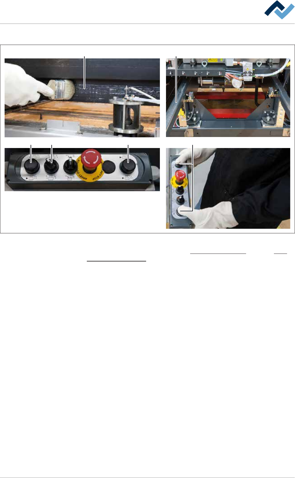
Fig.149: Clean the packing collar, then remove the solder pot
With regard to this, please read Chapters Cleaning agents used [
}300] and Tools
and auxiliary materials [}301].
ü Maintenance preparation
a) Wear protective clothing.
b) Cordon off the work area with a red and white safety chain and a warning sign.
c) Activate the module service via the terminal.
ð Move the solder pot to position [Service]
d) Open the doors and hoods in the area of the soldering module.
e) Open the gassing hood cover.
ð If the machine has the [Setup control] option:
f) Remove the RFID chips from the chip reader.
ð Please note: The parts coming into contact with solder can be cleaned
more easily as long as they are still hot!
g) Clean the packing collar (1) with a brush. Clean the packing collar on the out-
side and on all sides as thoroughly as possible.
h) Also clean the inside of the packing collar.
ð You can reach the inner area after opening the gassing hood lid.
ð Solder residues fall into the solder bath.
i) Position the solder pot trestle (2) and engage it.
j) Turn the switch (3) to the position shown on the control console.
k) Press and hold both buttons (4) simultaneously.
ð The solder pot is now conveyed out of the machine and will automatically
stop in its end position.
Ersa GmbH Operating Instructions_VF335_en|Rev. 14|30/11/2017 402/695

8|Service and maintenance
l) Release the buttons (4).
ð The process has now been completed.
Ersa GmbH Operating Instructions_VF335_en|Rev. 14|30/11/2017 403/695
8|Service and maintenance
Disassembling the nozzle plate
1
2
24
3
7AA
5 6
88
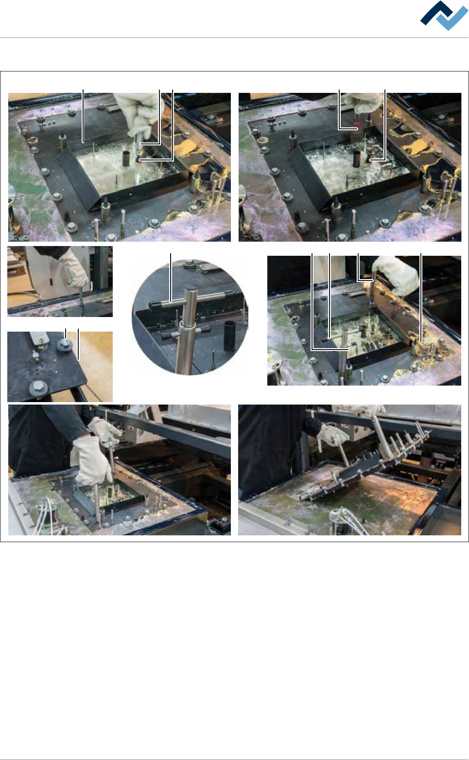
Fig.150: Disassemble the nozzle plate. Always hold bolted removing tools by the upper toggle (A)!
ü To disassemble the nozzle plate:
a) Remove any solder from the baffle frame (1). To do so, open the drain screw
(2) with a socket spanner (3).
b) Unlock all bayonet catches (5) with the socket spanner. Align the bayonet
catches so that the slots of the bolts (5) are parallel to the edges (6) of the
nozzle plate.
c) If necessary, convey any soiling (oxides, dross) into the solder bath using a silic-
one brush (4).
ð As soon as the solder has run out of the baffle frame:
d) Close the drain screw (2) and remove the socket spanner (3).
e) Place the two removing tools (8) on the nozzle plate and lock them.
Ersa GmbH Operating Instructions_VF335_en|Rev. 14|30/11/2017 404/695