Operating Instructions_VF335_en.pdf - 第127页
6|Function description 6.4 Visualization of the control processes The visualization and operation of the control processes is performed by means of the control software. It enables the comfortable operation and supervi…
6|Function description
6.3.7 Function and dialog descriptions
Profile
User administration
Logging
File path
General settings
Settings
User maintenance mode
Preheating
Soldering module
Exit
Default
11
1
Function and dialog descriptions are always written in squared brackets; e.g.:
– [Profile]
– [User administration]
– [File path]
– [Logging]
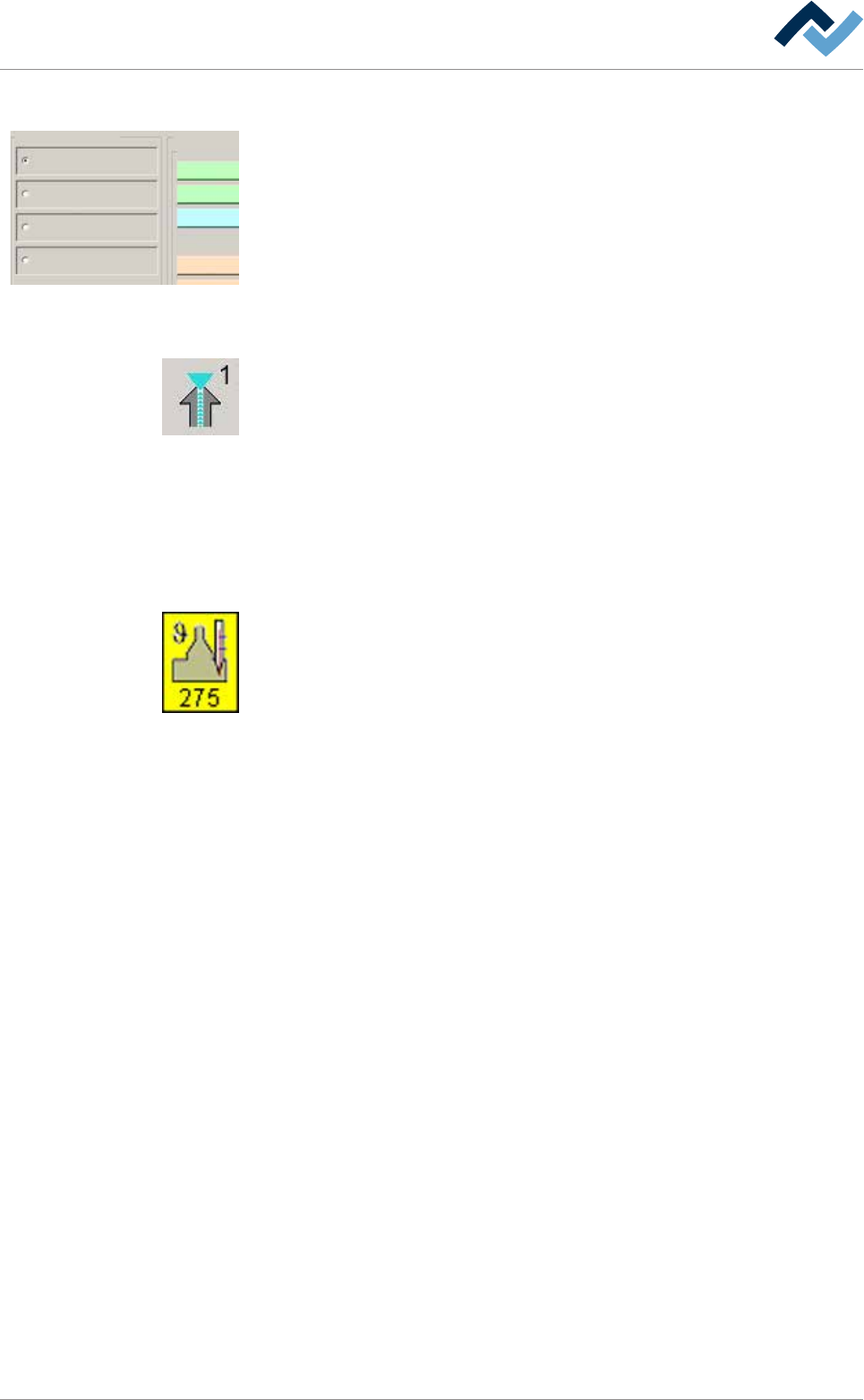
6.3.8 Buttons
Buttons are usually square and, with a few exceptions, contain icons or text indicat-
ing their functions. Buttons may have the following functions:
– Modules are enabled or disabled with a click on their respective buttons. If a
module is enabled, its respective button is displayed in yellow.
– Dialogs can be opened or closed by clicking on the corresponding buttons.
– Other functions are carried out.
This instruction manual will always describe the functions of a button first.
6.3.9 Symbols
Symbols are rectangular. They only appear in the start dialog and contain icons in-
dicating their function, in this example a soldering module. Symbols have two func-
tions:
– Dialogs can be opened with a click on the symbols.
– Inside the symbols, actual values such as the current solder temperature can
be displayed.
6.3.10 Operating instructions
the operating instructions contain:
– references to the measures to be adopted
or
– instructions to be followed by all means.
The operating instructions are structured as follows:
ü this symbol means: prerequisite for the implementation of a measure or
ü aim of a measure.
a) This symbol means: description of a measure.
ð This symbol means: intermediate result.
ð This symbol means: result.
An example: pressure adjustment
ü Remove the cover panel.
a) Adjust the (A) regulator air pressure to 2.5 bar.
ð The symbol on the screen turns green.
b) Reinstall the cover panel.
ð The air pressure has been properly set.
Ersa GmbH Operating Instructions_VF335_en|Rev. 14|30/11/2017 126/695
6|Function description
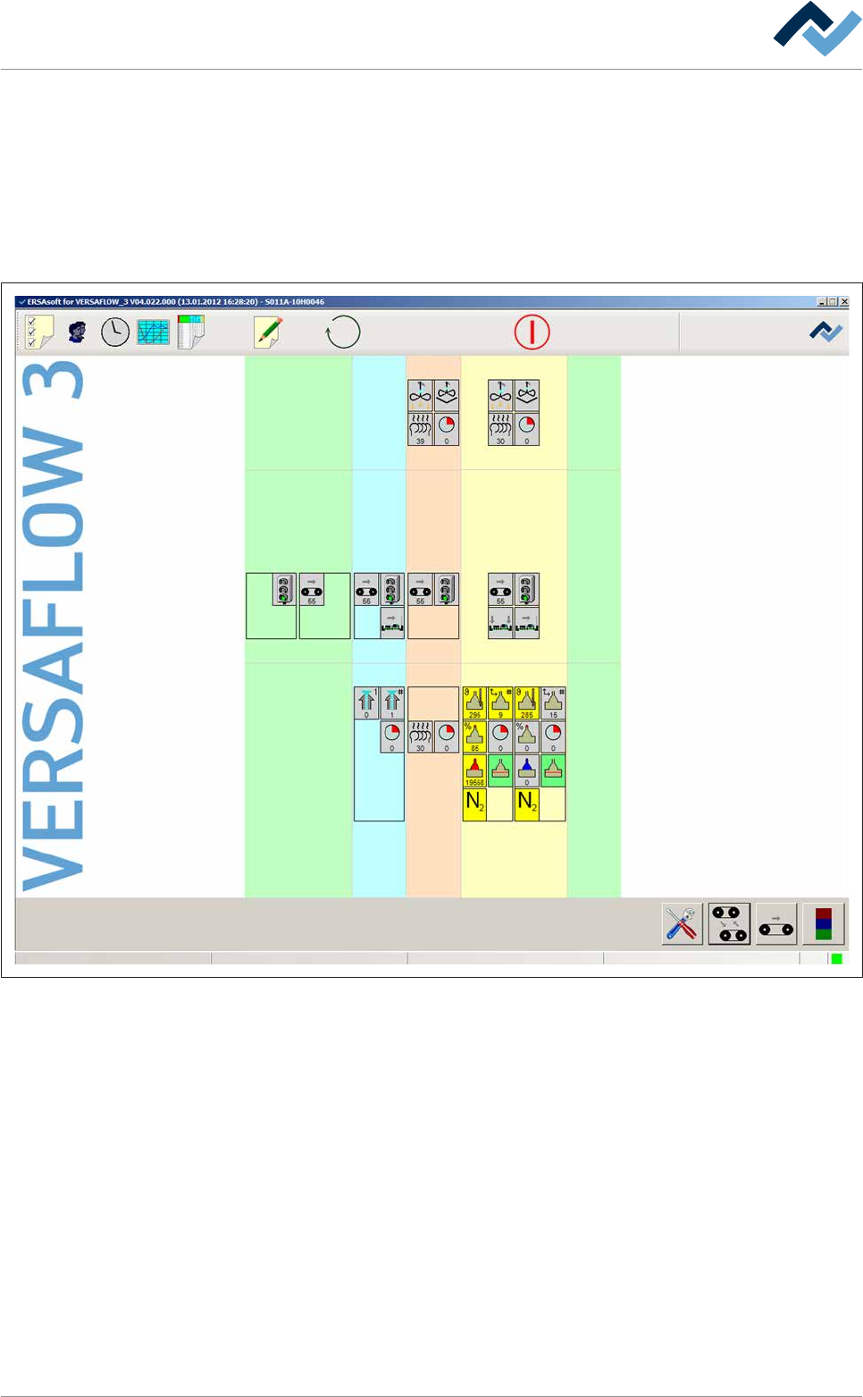
6.4 Visualization of the control processes
The visualization and operation of the control processes is performed by means of
the control software. It enables the comfortable operation and supervision of all
work processes.
The starting point of the user interface is always the start dialog. This is the start
window from which comfortable branching to further dialogs is possible. In this
start dialog, the machine and its individual units are displayed schematically.
Preheating Soldering module ExitInfeed Infeed unit
Solder pot
user: none
Flux unit
Maintenance mode
Fig.20: The start dialog of the control software:
In the above example, the machine is divided into the following sections:
– Infeed
– Infeed unit
– Flux unit
– Preheating
– Soldering module
– Exit
Ersa GmbH Operating Instructions_VF335_en|Rev. 14|30/11/2017 127/695
6|Function description
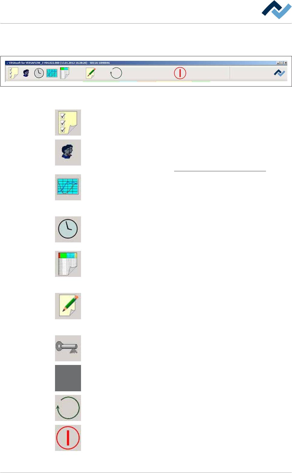
6.4.1 Top toolbar
This toolbar is located in the upper part of the start dialog:
Preheating Soldering module ExitInfeed Infeed unit
Solder pot
user: none maintenance mode
Flux unit
Fig.21: Top toolbar
The top toolbar contains the following buttons:
Configuration. Click on this button to open the [Configuration] dialog. Only trained
and qualified ERSA GmbH personnel may change the configuration of the machine.
General settings. Click on this button to open the [General settings] dialog. In this
dialog, you can create and administer users, determine the user language and col-
ours as well as the storage locations for process data and soldering programs.
On this regard, please read chapter The [General settings] editing dialog [
}131].
Process recorder. Click this button to open the [Process recorder] dialog. The pro-
cess recorder is used to record produced readings and to graphically display the re-
corded results. You can filter out individual readings to improve clarity. The read-
ings are saved automatically and can later be retrieved and printed for comparison.
On this regard, please read chapter The process recorder.
Weekly timer. Click on this button to open the [Weekly timer] dialog. In this dialog,
you can determine the current time as well as the switch-on and switch-off times
for the machine.
On this regard, please read chapter The [Weekly timer] setting dialog.
Edit soldering program. Click on this button to open the [Edit soldering program]
dialog. In this dialog, you can create soldering programs or edit and change existing
soldering programs. Several soldering programs can be combined into a library to
improve clarity.
On this regard, please read chapter The soldering program editor
Process data. Click on this button to open the [Process data] dialog. This function
allows the exact logging and documentation of the entire soldering process. You
can monitor, export and print the data of a manufacturing batch. You can have a
separate process data file generated automatically for each board of a series.
On this regard, please read chapter .
User log off. Click on this button to open the [User log off] dialog. Click on this but-
ton to log out the currently logged in user. The key disappears and the button is
then displayed in grey.
No user logged in. If no user is logged in, the key symbol is not visible. The button is
then displayed in grey.
Click on this button to change the operating mode of the machine or select a sol-
dering program.
On this regard, please read chapter Selecting and starting a soldering program
When the red symbol appears, the machine is in the [Maintenance mode] operat-
ing mode. By clicking on this button, you can switch to the [Movement off] operat-
ing mode.
Ersa GmbH Operating Instructions_VF335_en|Rev. 14|30/11/2017 128/695