Operating Instructions_VF335_en.pdf - 第531页
9|Spare and wear parts Second stopper left, (segmented preheating), view [Y], [Z] 1 2 8 9 3 4 7 7 6 5 7 4 6 5 Fig.252: EM113-37-04-00a Pos Designation Item number A B 1 Joint clip 170367 x 2 Swivel head M6 170366 x 3 …
9|Spare and wear parts
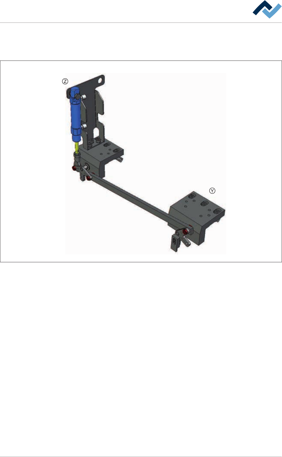
9.5.2.7 Second stopper left, (segmented preheating)
Overview
Fig.251: EM113-37-04-00
Ersa GmbH Operating Instructions_VF335_en|Rev. 14|30/11/2017 530/695
9|Spare and wear parts
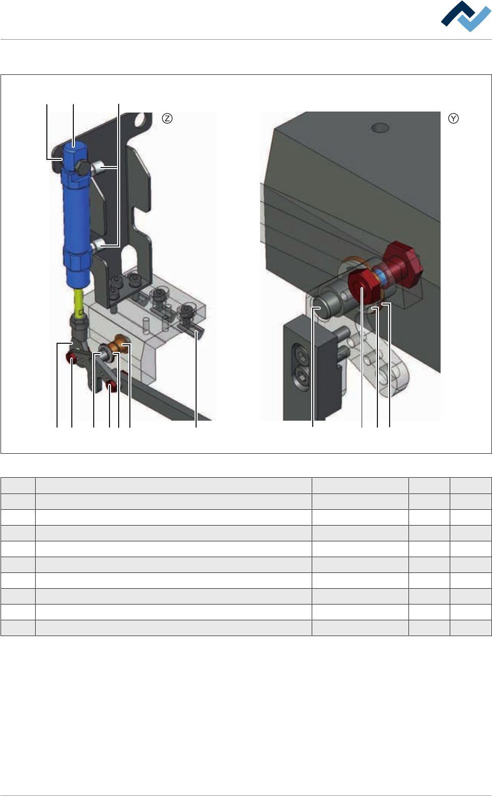
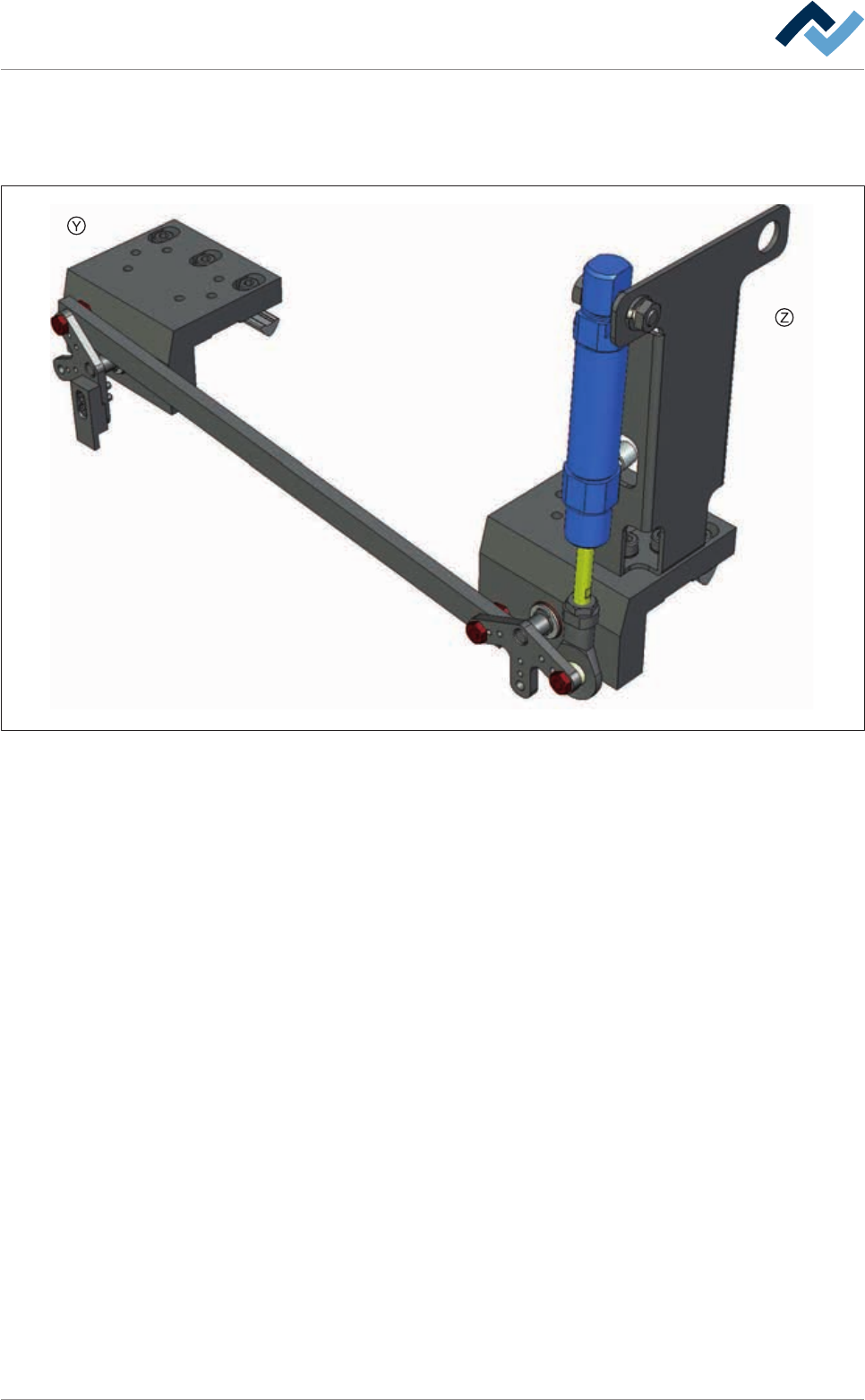
Second stopper left, (segmented preheating), view [Y], [Z]
1
2
89
3
4
7 7 65
7
4
6
5
Fig.252: EM113-37-04-00a
Pos Designation Item number A B
1 Joint clip 170367 x
2 Swivel head M6 170366 x
3 Groove nut STM5 6ZIS049 x
4 Washer 8/14X1,0 DIN988 6SA08X1.00 x
5 Circlip A 8x0,8mm, DIN 471 6SER-A080471 x
6 Collar bush 143513 x
7 Pan head screw M5 170207 x
8 Straight screwing M5, stainless stell 97965 x
9 Cylinder, 2-acting Ø 16, stroke=20 Temp. resistant 85950 x
Ersa GmbH Operating Instructions_VF335_en|Rev. 14|30/11/2017 531/695
9|Spare and wear parts
9.5.2.8 Second stopper right, (segmented preheating)
Overview
Fig.253: EM113-37-03-00
Ersa GmbH Operating Instructions_VF335_en|Rev. 14|30/11/2017 532/695