Operating Instructions_VF335_en.pdf - 第107页
5|Commissioning 5.3.10.8 Check stoppers and board fixation We explain this process using the example of a soldering unit. Check all the stop- pers available on the machine in the same way. ü First set the width adjustm…
5|Commissioning
5.3.10.5 Check the compressed air heater (optional)
ü To check the compressed air heater, proceed as follows:
a) Click on
under [Soldering module] in the start dialog.
ð The [Heating] input dialog (top) appears.
b) Click on
under [Heating].
ð The heater is turned on, the button is displayed in yellow. At the same
time, under [Convection], also button
is shown in yellow.
c) Click on
under [Convection].
ð The [Increase convection] is turned on and the button is displayed in yel-
low.
d) Under [Heating], enter a set value in the [Temperature] input field.
e) Compare the actual value with the entered set value.
ð The actual value has to change.
f) In the heater frame, click on
.
ð The heater and convection are turned off.
Click on
to close the dialog.
5.3.10.6 Checking the solder temperature
ü To check the solder temperature, proceed as follows:
a) Click on the symbol of the soldering module and enter a temperature set value
in the [Solder pot] input dialog.
b) Turn on the pot heater by clicking on
. In this respect, compare the actual
values with the entered set values.
ð When the heater is on, the symbol is displayed in yellow. After consider-
able time, the displayed actual temperature value must change.
5.3.10.7 Enabling the nitrogen supply
ü To enable the nitrogen supply, proceed as follows:
a) Adjust the correct pressure of the nitrogen supply on the maintenance unit. On
this regard, please read Chapter Protective gas technology (nitrogen) [
}26].
b) Click on the soldering module symbol and, under [Switch functions], click on
[
] to enable the nitrogen supply.
ð When the nitrogen supply is enabled, the symbol is displayed in yellow.
Ersa GmbH Operating Instructions_VF335_en|Rev. 14|30/11/2017 106/695
5|Commissioning
5.3.10.8 Check stoppers and board fixation
We explain this process using the example of a soldering unit. Check all the stop-
pers available on the machine in the same way.
ü First set the width adjustment and insert the board into the infeed of the ma-
chine.
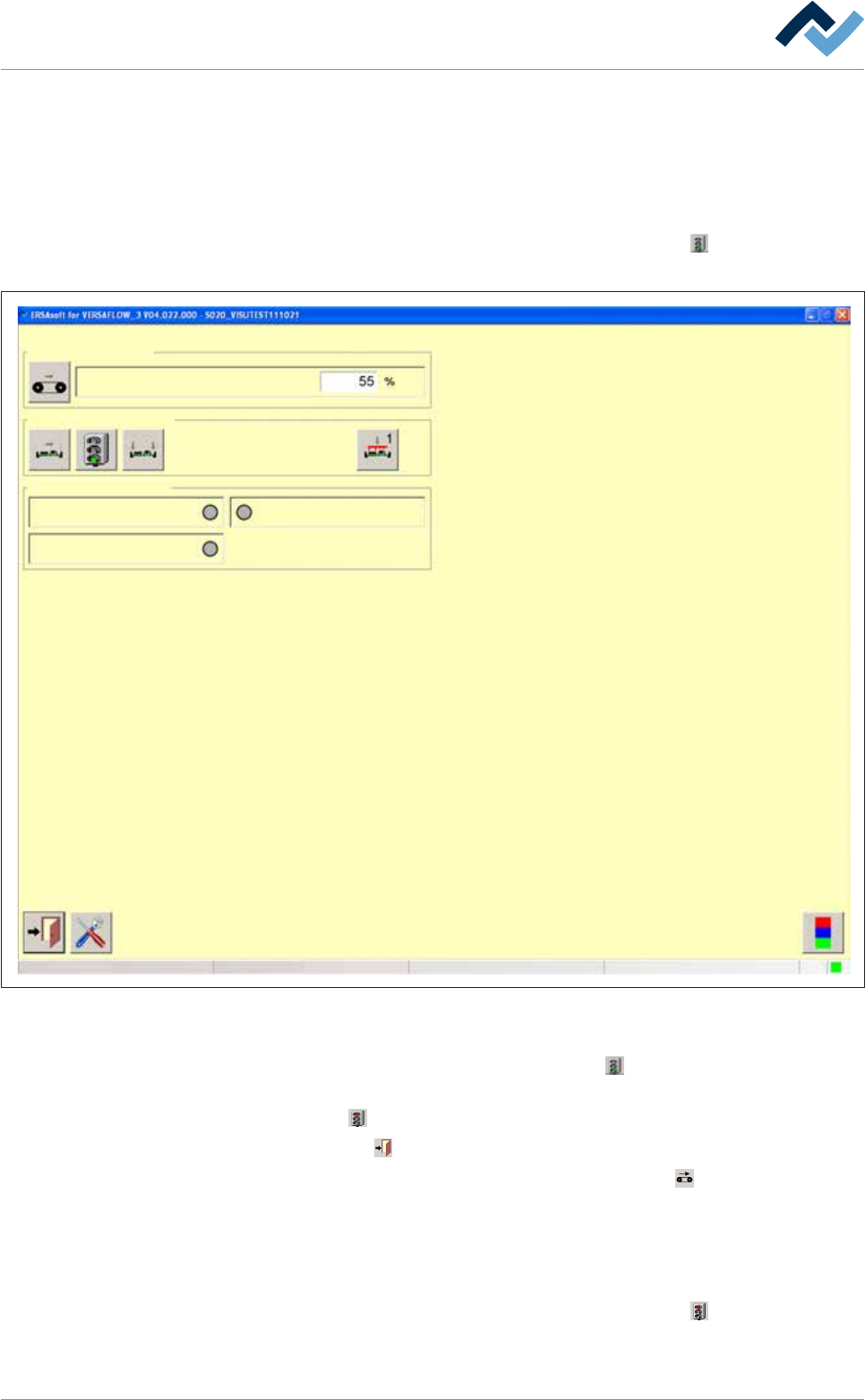
a) In the start dialog, in the [Soldering] frame, click on the
button. The [Solder-
ing module] input dialog is displayed:
Edit dialog Soldering module
Conveyor speed
Conveyor
Switch functions
PCB in moduleSensors
Hardware signal
Module not empty
Software signal
user:
none
Maintenance mode
Fig.18: The input dialog
ü To check the stopper and board fixation:
a) In the [Switch functions] frame, click on the
button.
ð In doing so, the stopper is closed on the soldering unit. The button changes
into
.
b) Click on the
button to close the dialog.
c) In the start dialog, in the bottom toolbar, click on the
button to start all con-
veyors together
ð The board is then transported to the soldering unit and halted there by the
stopper.
d) Stopping the conveyor.
e) In the start dialog, in the [Soldering] frame, click on the
button. The [Solder-
ing module] input dialog appears.
Ersa GmbH Operating Instructions_VF335_en|Rev. 14|30/11/2017 107/695

5|Commissioning
f) In the [Switch functions] frame, click on the button to laterally fix the board.
Then, click on the
button to fix the board above / below.
ð Once the board has been fixed, the buttons turn yellow.
g) After guaranteeing all the functions, you can disable the stoppers and fixations,
and move the board out of the machine.
Ersa GmbH Operating Instructions_VF335_en|Rev. 14|30/11/2017 108/695