Operating Instructions_VF335_en.pdf - 第491页
9|Spare and wear parts Z-axis eccentric solder pot (double travel, single track) 1 1 8 8 9 7 4 4 1 2 2 5 7 3 3 Fig.217: EM113-22-01-00a Pos Description Item number A B 1 Plastic disk 182126 x 2 Shock absorber 182130 x…
9|Spare and wear parts
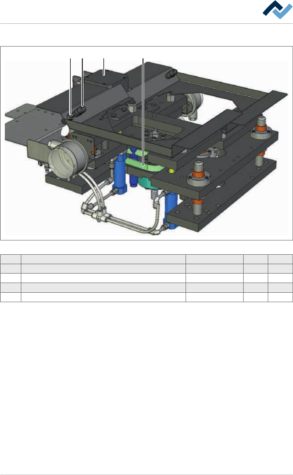
9.4.7 Z-axis excenter solder pot (double stroke, single track)
12 3 4
Fig.216: EM113-22-01-00
Pos Description Item number A B
1 Tooth belt 425-5M-15 6ZR0425-5M-15 x
2 Connector, M10 x 1 182134 x
3 Coupling M10 x 1 182135 x
4 Servo drive with resolver 23567 x
Ersa GmbH Operating Instructions_VF335_en|Rev. 14|30/11/2017 490/695
9|Spare and wear parts
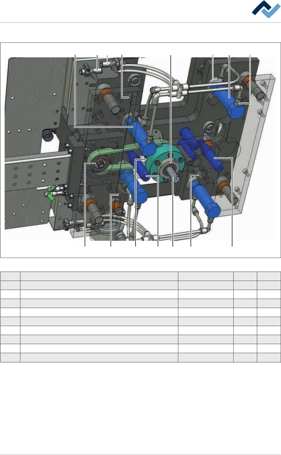
Z-axis eccentric solder pot (double travel, single track)
1
1
8 8 9 7
4 4 1 22 5
7 33
Fig.217: EM113-22-01-00a
Pos Description Item number A B
1 Plastic disk 182126 x
2 Shock absorber 182130 x
3 Straight edge connector 116079 x
4 Tensioning kit 112207 x
5 Lifting spindle, complete * 209659 x
6 Ball nut * 184736 x
7 ISO-Cylinder 182132 x
8 One-way restrictor 6BO548 x
* Cannot be ordered separately
Ersa GmbH Operating Instructions_VF335_en|Rev. 14|30/11/2017 491/695
9|Spare and wear parts
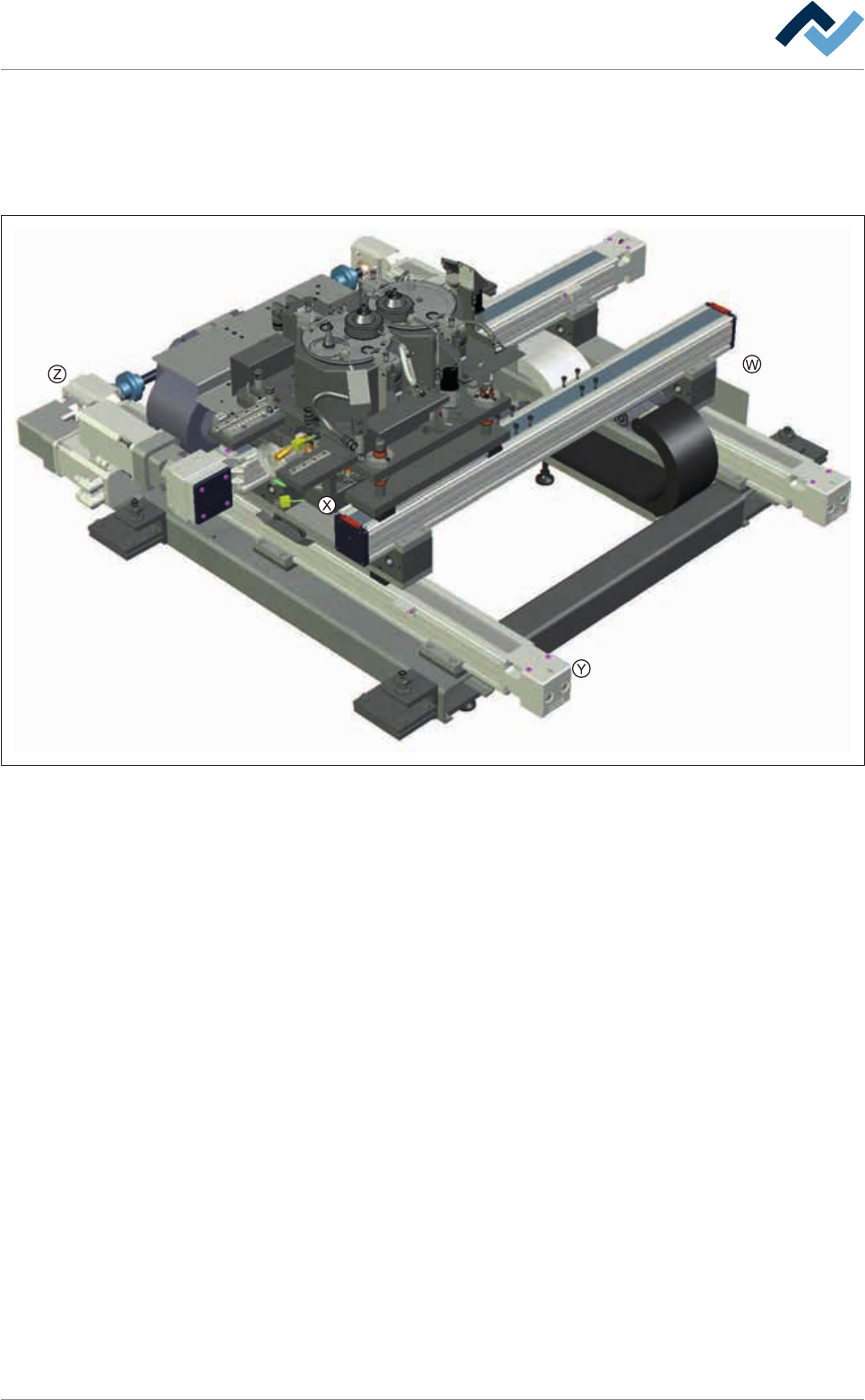
9.4.8 Positioning system for double solder pots with eccentric solder pot lids, y-
variable
Overview
Fig.218: EM113-23-00
Ersa GmbH Operating Instructions_VF335_en|Rev. 14|30/11/2017 492/695