Operating Instructions_VF335_en.pdf - 第239页
6|Function description NOTE Why are the [Positioning] and [Special positions] frames not displayed? a) This can have several causes: ð Your machine does not have a program-controlled width adjustment. ð The program-con…
6|Function description
WARNING
Danger of crushing! Risk of injury due to squeezing of body parts!
CAUTION
Risk of material damage!
Trapped or falling down boards may cause damage to the machine.
a) Before adjusting the conveyor width, make sure that no board is in the machine!
ü To manually adjust the conveyor width in the jog mode:
a) In the [Step mode] frame, enter a value in [mm/s] into the [Set value] input
field.
b) Click and hold the
or button.
ð As long as the button is clicked, the conveyor width is adjusted at a speed of
[Set value] Here, a ramp function is used. The speed gradually increases up to
[Set value]. In the display field [Actual value],you can read the current speed in
[mm/s].
ü To manually adjust the conveyor width to a defined set value:
a) In the [Step mode] frame, enter a value in [mm/s] into the [Set value] input
field.
b) In the [Positioning] frame, enter a value in [mm/s] into the [Set value] input
field.
c) Click on the
button.
ð The conveyor width is now adjusted. In the display field [Actual value], you can
read the conveyor current width in [mm]. During the adjustment, the symbol
appears next to a moving axis.
Referencing must then always be carried out:
– After a breakdown of the CAN motors power supply
– after pressing the emergency STOP
– after a power failure
– after switching off the main switch
– after an adjustment
ü To reference width adjustment:
a) In the [Reference move] frame, click on the
button.
ð Referencing is started.
NOTE
The travel movement requires a certain amount of time.
a) In the meantime, do not perform any inputs.
b) During referencing, the
symbol is displayed next to a moving axis in the setting
dialog.
Ersa GmbH Operating Instructions_VF335_en|Rev. 14|30/11/2017 238/695

6|Function description
NOTE
Why are the [Positioning] and [Special positions] frames not displayed?
a) This can have several causes:
ð Your machine does not have a program-controlled width adjustment.
ð The program-controlled width adjustment has not been configured.
ð The [Enable only step mode] checkbox is enabled in the settings dialog.
Ersa GmbH Operating Instructions_VF335_en|Rev. 14|30/11/2017 239/695
6|Function description
6.14.8 The settings dialog [Width adjustment]
În this dialog you can set the width adjustment.
NOTE
Are any changes possible?
To access this dialog, the [Module properties] and [Set value pages] user rights are re-
quired. The settings can only be displayed, without user name and password. In this
case, while the password prompt appears, press the [ESC] key on your keyboard or
click on the [Cancel] button.
ü To open the [Conveyor width adjustment] input dialog:
a) In the [Conveyor width adjustment] frame, click on the
button.
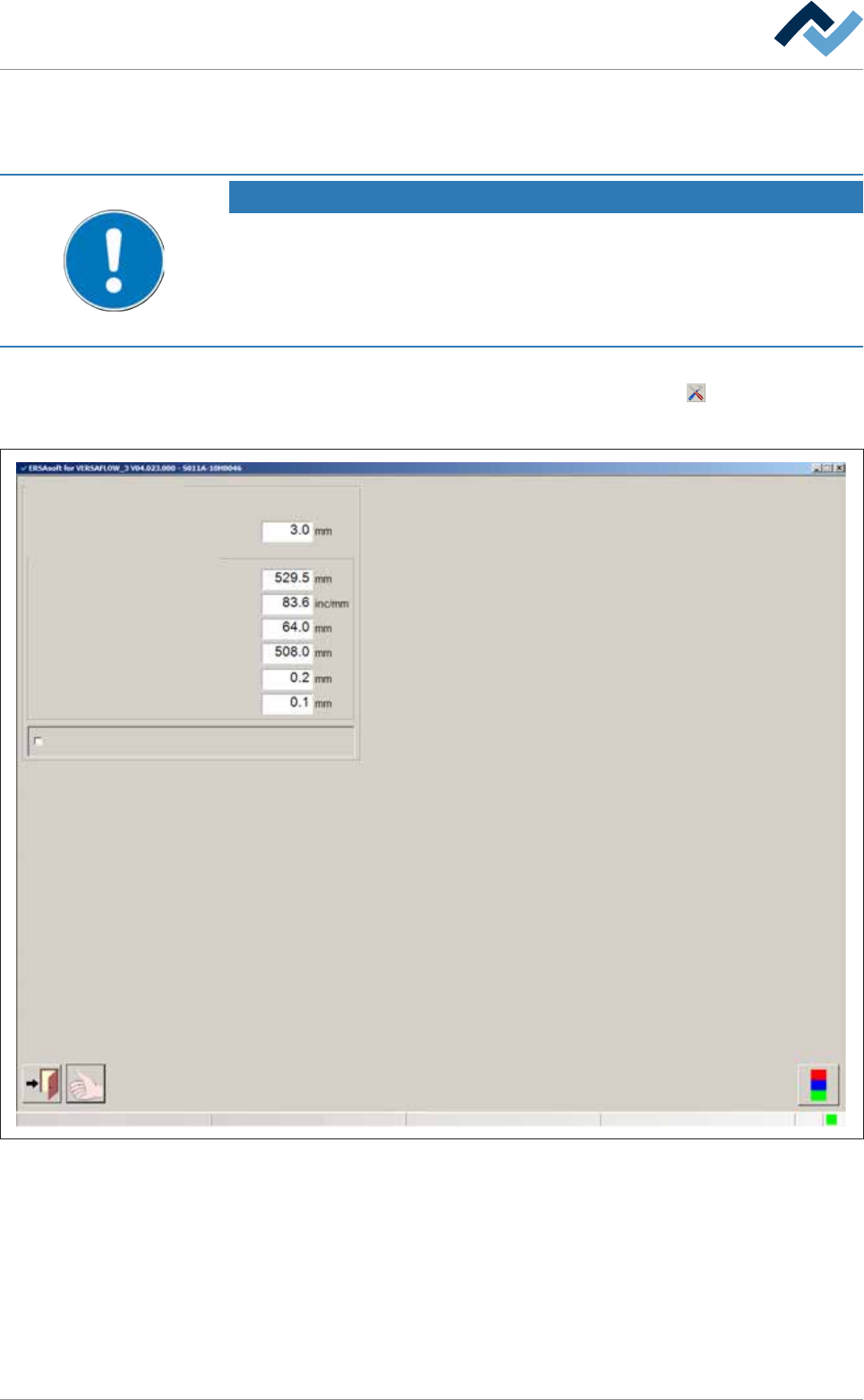
ð The [Conveyor width adjustment] input dialog is displayed:
Conveyor width adjustment
User ersa
Position measuring and ranges
Conveying edge
Offset
Gradient
Position min.
Position max.
Min. difference for positioning
Position window
Enable only step mode
Maintenance mode
Fig.60: The settings dialog [Width adjustment].
ü To set the [Conveying edge]:
a) Enter the width of the conveyor supports (length of chain pins) in [mm] into
the input field.
ð The travel range of the soldering units is limited by this value in order to pre-
vent a collision between the solder nozzle and the conveyor chains. The dia-
meter of the solder nozzle is therefore taken into account. If a conveyor chain
is used with longer chain pins, you need to adjust this value.
Ersa GmbH Operating Instructions_VF335_en|Rev. 14|30/11/2017 240/695