Operating Instructions_VF335_en.pdf - 第180页
6|Function description Table of power value IR element graduation Heating Time 60 30 0 30 30 60 0 80 Fig.39: Power value table Click on to close the dialog. Ersa GmbH Operating Instructions_VF335_en|Rev. 14|30/11/…
6|Function description
ð When the soldering program is started, the module is pre-heated to this tem-
perature. The [Standby temperature] is kept at this value in the [Automatic
mode] operating mode. This ensures that the same initial conditions always
prevail in the module.
First always empty the next module
ü The PCBs shall only be fed into the next module if this module is empty:
a) Activate the [Empty module always] checkbox.
ð The PCBs will only be fed into the module it the next module is empty. This
way, the PCBs are prevented, for example, from remaining too long in the
module due to a jam. However, this function can extend the cycle times.
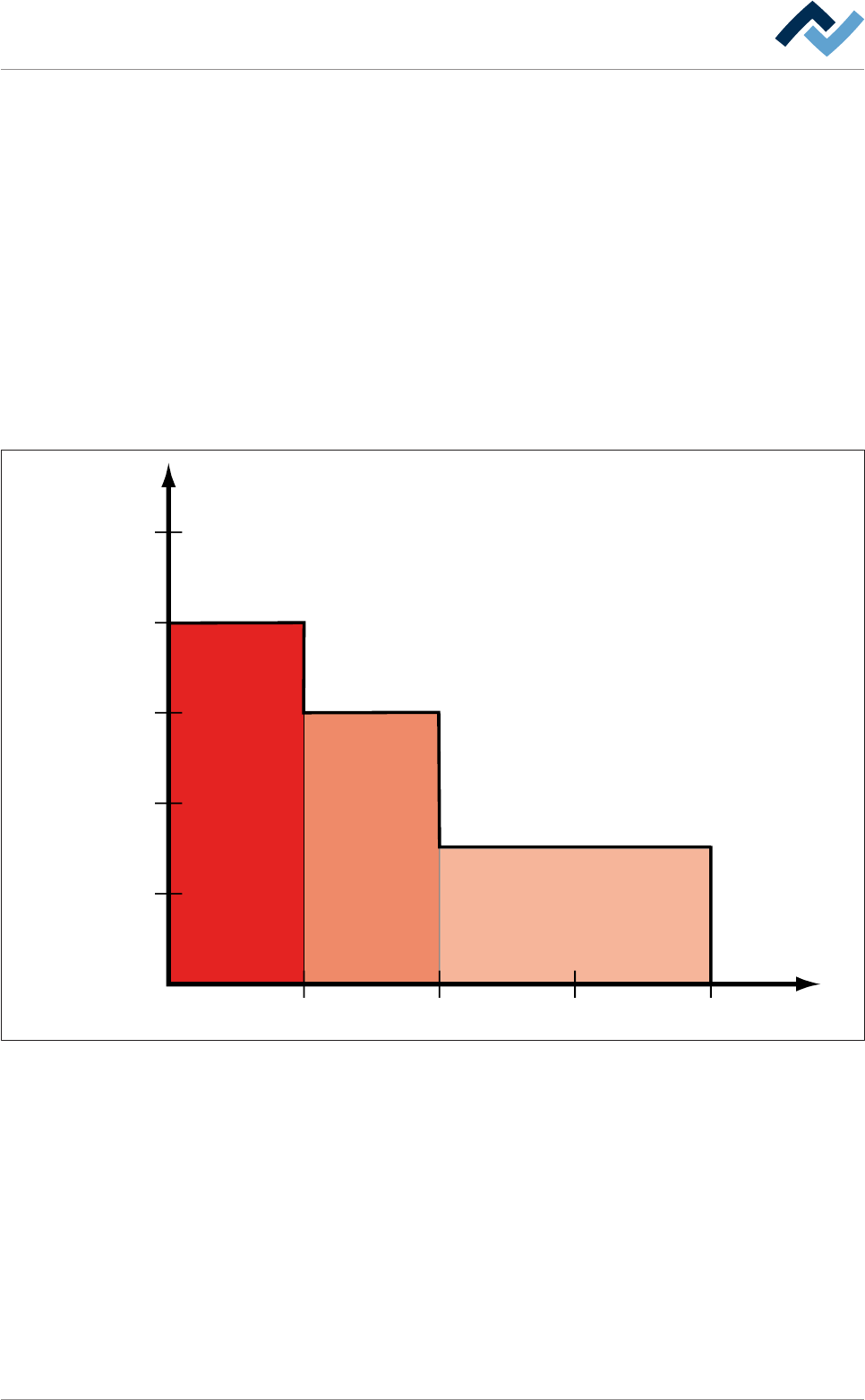
In the [Table of power value] frame, you can set a power value/time profile for the
heater. For each active segment of the preheater, you can enter a power value as a
[%] and a time in [s]:
20
30 60 90
40
60
80
100
#1 #2 #3
Power value (%)
120 Time (s)
Compare the values shown here with the table in the [Table of power value] frame:
Ersa GmbH Operating Instructions_VF335_en|Rev. 14|30/11/2017 179/695

6|Function description
Table of power value
IR element graduation
Heating
Time
60
30
0
30
30
60
0
80
Fig.39: Power value table
Click on
to close the dialog.
Ersa GmbH Operating Instructions_VF335_en|Rev. 14|30/11/2017 180/695

6|Function description
6.9.9 Soldering unit settings
In this example, the soldering module is provided with a compressed air heater
above and two pots.
Enabling the module
ü To enable the module:
a) In the [General soldering program data] dialog, activate the checkbox of the
module in level 1.
ð The module has now been enabled and is used in the soldering program.
Setting preheating temperature, preheating period
ü To set the preheating temperature and period:
a) In the [General soldering program data] dialog in level 2, click on the input
fields and enter the preheating temperature in [°C] and the prehating period in
[s].
ð The PCBs will thus be subjected from above to the preheating temperature for
the duration of [Preheating time].
Setting the conveyor speed
ü To set the conveyor speed:
a) In the [General soldering program data] dialog in level 3, click on the input field
of the conveyor section.
b) Enter the conveyor speed in [%] of the maximum possible speed value.
ð This is the speed at which the board is conveyed into the next module.
Enabling pots
ü To enable one or both pots:
a) Enable checkboxes in the [General soldering program data] dialog in level 4.
ð If a checkbox is enabled, the relevant pot is used in the soldering program.
Performing extended settings in the [General additional data] dialog
ü To perform extended settings:
a) Open the [General soldering program data] dialog.
b) Below Level 6, click on the
button in the corresponding module.
Open the [General additional data] dialog. The yellow square provides information
about how often the dialog has already been opened.
Ersa GmbH Operating Instructions_VF335_en|Rev. 14|30/11/2017 181/695