Operating Instructions_VF335_en.pdf - 第224页
6|Function description – [Waiting time congestion successor] (N+1) shows the delay time up to counter start. An example: ü The [Waiting time while production mode] (N-1) delay time shall be 3 seconds. a) Enter value 3 …
6|Function description
Reading working times in the [Running times] frame
In this frame, you can read the following:
– [Time in maintenance mode] shows how long the machine has been in the
[Maintenance mode ] operating mode since commissioning.
– [Time in production mode] shows how long the machine has been in the oper-
ating mode [Automatic mode] and how long it has been soldering.
– [Waiting time while production mode] (N-1) shows how long the machine has
been in the [Automatic mode] operation mode and has not been soldering be-
cause no more PCBs were delivered by the upstream system.
– [Waiting time congestion successor] (N+1) shows how long the machine has
been in the operating mode [Automatic mode] and has not been soldering be-
cause PCBs could not be removed by the downstream system.
– [Total time] shows the machine operating hours since commissioning.
Reading piece numbers in the [Numbers of Boards] frame
In this frame, you can read the following:
– [Currently in machine] shows how much solder material is currently inside the
machine.
– [Total boards] shows how much solder material has been processed error-free
since commissioning.
– [Produced boards] shows how much solder material has been processed error-
free since commissioning.
– [Defective boards] shows how much solder material has been processed error-
free since commissioning.
Changing times and counter readings
ü To change times and counter readings:
a) Click on the
button in the bottom toolbar.
ð Editable input fields appear now highlighted in white.
b) Click on the desired input field and enter the value.
ü Accept settings, close dialogs
a) Click on
to accept a setting.
b) Click on
to close a dialog.
NOTE
Why may discrepancies result in the counter readings?
If boards are removed from the machine during the production process, counting dif-
ferences between the boards fed into the machine and those actually produced may
result. Counter readings can therefore be changed. If counter readings were changed,
counting is continued from the counter reading which you entered.
Delayed counters start in the [Delay time to counter start] frame
For the [Waiting time while production mode] (N-1) and [Waiting time congestion
successor] (N+1), you can enter a delay time into the [Running times] frame. When
the event occurs, the counter starts only when time is up.
In this frame, you can read the following:
– [Waiting time while production mode] (N-1) shows the delay time up to
counter start.
Ersa GmbH Operating Instructions_VF335_en|Rev. 14|30/11/2017 223/695

6|Function description
– [Waiting time congestion successor] (N+1) shows the delay time up to counter
start.
An example:
ü The [Waiting time while production mode] (N-1) delay time shall be 3 seconds.
a) Enter value 3 in the input field.
ð If the upstream system delivers no more boards, the above time begins to run.
If after 3 seconds still no PCBs are available at the infeed, the [Waiting time
while production mode] time is started in the [Running times] frame.
Ersa GmbH Operating Instructions_VF335_en|Rev. 14|30/11/2017 224/695
6|Function description
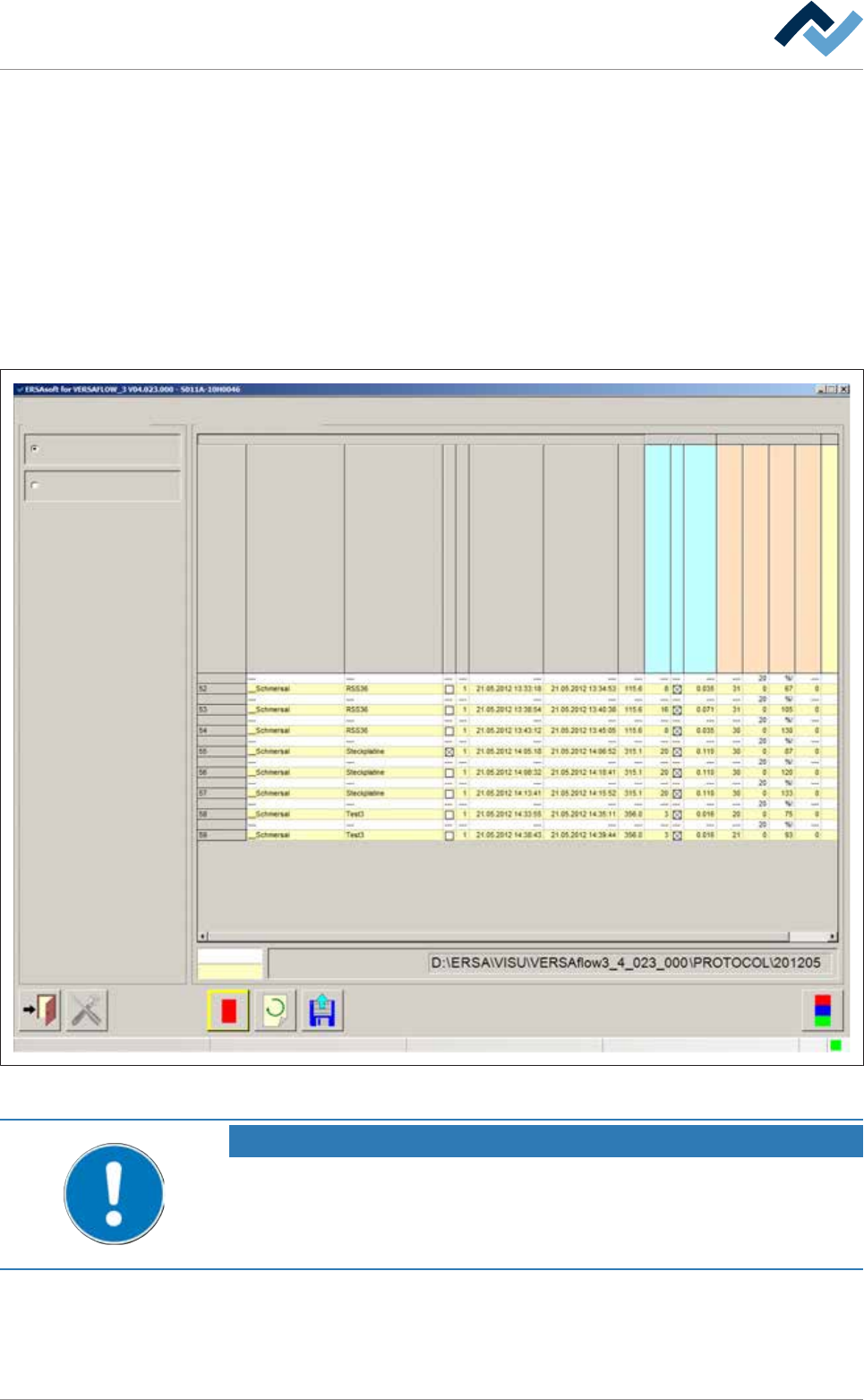
6.13.2 The soldering report
This function allows a precise logging and documentation of the entire production
process. You can monitor and export the data of a manufacturing batch. You can
have a separate process data file generated automatically for each PCB of a series.
Opening the dialogue
ü Opening the [Soldering report] edit dialogue:
a) Activate the [Soldering report] radio button in the [Soldering report and oper-
ating data] edit dialogue.
ð The machine soldering report is displayed:
Soldering report and operating data Soldering report
Soldering reportSelection
Soldering report
Operating data
Set value
Actual value
File name
user:
Service
Maintenance mode
Serial board number
Library
Program
Error
Number
Running in moment
Running out moment
Conveyor width [mm]
Time in fluxer unit [s]
Flux head 1 active
consumption Flux head 1
Time in preheat unit 11 [s]
Temp. in upper preheat unit 11 [°C]
Temp. in lower preheat unit 11 [°C]
No. PH repetitions preheat unit 11
Time in soldering unit 1 [s]
Fig.56: The soldering report. In this dialog, the soldering report is shown in tabular form.
NOTE
Are any changes possible?
The [Set value pages] user rights are required to access this dialog. Settings can only
be displayed if no name and password are logged in. In this case, press the [ESC] key
on your keyboard, or click on the button [Cancel] when a password is required.
Ersa GmbH Operating Instructions_VF335_en|Rev. 14|30/11/2017 225/695