Operating Instructions_VF335_en.pdf - 第253页
6|Function description – [Test tolerance plus] and [Test tolerance minus]: These two values define the range in which the solder waves height test is to be performed. The minus tol- erance thereby specifies how much of…
6|Function description
Test Abstand Z [mm]
– [Test distance [mm]]: This value indicates how far the test needle lies above
the upper edge of the nozzle during the solder wave height test. It also defines
the height of the solder wave. A value pf about 3 mm is recommended. For
nozzles with an inner diameter below 3 mm, this value should be reduced by
0.5 mm. For nozzles with an inside diameter above 8 mm, this value should be
increased by 0.5 mm.
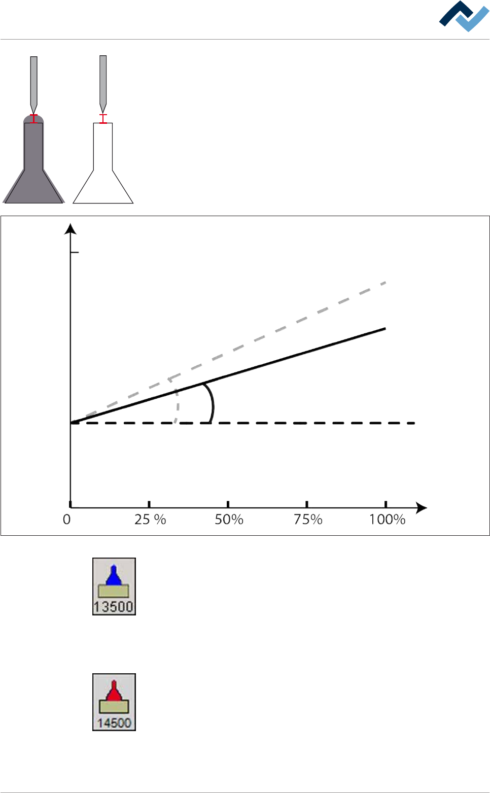
– [Gradient]: This value determines how much the control power of the pump in-
creases when the wave power (%) is increased by 1%. The larger the Gradient,
the greater the increase in the control power and vice versa. The following fig-
ure illustrates the relationships:
Gradient
Offset
Wave power
30000
Control
Pump
Pump
Control
Soldering nozzle
Soldering nozzle
(B)
(A)
Fig.67: Diagram
– [Offset cold], you will find this button in the start dialog: This value indicates
the control power of the solder pump in cold condition. It is a static value. Off-
set cold is used if the solder pump is started after it has been previously turned
off for a while. After the first successful solder wave height test, the pump has
warmed and Offset warm is used. Offset cold is always under the value of Off-
set warm because the control power required is lower in a cold operating con-
dition. If the solder pot icon is blue, the solder pot is still regarded as cold and
[Offset cold] is used. The number under the icon indicates the currently active
Offset cold. In this case, it is a purely numerical value without unit.
– [Offset warm], you will find this button in the start dialog: This value indicates
the control power of the solder pump in warm condition. It is a dynamic value.
This value is the result of the solder wave height tests. It is determined again
using each new test and automatically transferred to the nozzle table. If the
solder pot icon is red, the solder pot is regarded as warm and the [Offset
warm] is used. The number under the icon indicates the currently active Offset
warm. In this case, it is a purely numerical value without unit.
Ersa GmbH Operating Instructions_VF335_en|Rev. 14|30/11/2017 252/695

6|Function description
– [Test tolerance plus] and [Test tolerance minus]: These two values define the
range in which the solder waves height test is to be performed. The minus tol-
erance thereby specifies how much of the test is due to be started before the
set offset. The plus tolerance specifies how far the test is due to be run beyond
the set offset to determine the new offset before the test process is stopped.
As minus and plus tolerance values, 700 and 2000 are respectively recommen-
ded.
– [Test offset max.]: This value limits the maximum control power. The offsets
identified in the solder wave height test cannot exceed this value.
Ersa GmbH Operating Instructions_VF335_en|Rev. 14|30/11/2017 253/695

6|Function description
6.15.3 Prerequisites for installing a nozzle
If you want to install a new nozzle in the Data table solder nozzle, the following
prerequisites must be met:
– The machine is in the [Maintenance mode] operating mode
– The solder pump has reached the operating condition [warm]
– The solder has reached the required set temperature
– The needle for the solder wave height test must be free of contamination
– The test position of the nozzle must be set correctly; the needle for the solder
wave height test must be located above the centre of the nozzle and show the
[Test distance [mm]] set in the nozzle table.
– The new nozzle must be clean and wettable
– The new nozzle must be used and warm
Ersa GmbH Operating Instructions_VF335_en|Rev. 14|30/11/2017 254/695