Operating Instructions_VF335_en.pdf - 第425页
8|Service and maintenance 8.11.9.4 Connecting the cold solder pot to the (optional) heating station and preheating it NOTE Heating up the solder before replacing the DIP solder pot The solder can be heated up in the op…

8|Service and maintenance
b) To lift the replacement rack, push the lever (2) in direction (1) and move the
bar up and down until you reach the desired height.
c) To lower the replacement rack, push the lever (2) slowly in direction (3). The
replacement rack will be slowly lowered.
ð Always lower the replacement rack slowly and gently, in order to avoid any
damage to the replacement rack or the machine.
ð The process has now been completed.
Ersa GmbH Operating Instructions_VF335_en|Rev. 14|30/11/2017 424/695
8|Service and maintenance
8.11.9.4 Connecting the cold solder pot to the (optional) heating station and
preheating it
NOTE
Heating up the solder before replacing the DIP solder pot
The solder can be heated up in the optional heating station before replacing the DIP
solder pot. Here it remains solid, but becomes hot. A safety switch in the heating sta-
tion prevents the solder from heating and liquefying any further.
ü To connect the cold solder pot to the heating station and preheat it:
ü You have donned the required protective clothing
1 2
Type 702041
I ON
0 OFF
3 4 5
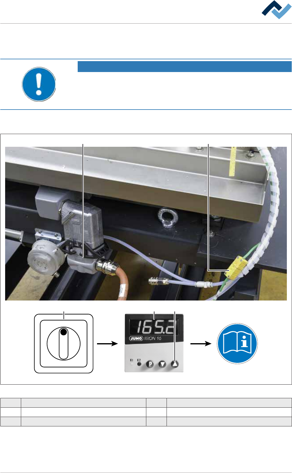
Fig.162: Connecting the cold solder pot to the heating station
1 Plug-in connectors for solder pot heating 4 JUMO temperature controller
2 Thermocouple 5 Start button
3 Main switch
ü
Ersa GmbH Operating Instructions_VF335_en|Rev. 14|30/11/2017 425/695
8|Service and maintenance
ü To connect the solder pot:
a) Using the lifting cart, bring the replacement rack with the cold DIP solder pot to
the heating station.
b) Shut off the area around the cold DIP solder pot with a red and white safety
chain and a warning sign.
c) Connect the thermocouple (2) to the solder pot.
d) Connect the plug of the solder pot heating (1) to the solder pot and lock it.
e) On the main switch (4), switch on the heating station.
f) The set temperature to which the solder must be brought is pre-set on the
temperature controller. With respect to this point, please also refer to the user
manual [91126] of the temperature controller. This can be found on the
[product_data_selective] data carrier, in the [JUMO] folder.
g) To start the heating process: Press the ▲ start button (5) on the temperature
controller.
ð When the set temperature is reached, it is shown in the display.
ð The process has now been completed.
NOTE
Setting the timer of the heating station
The heating station will start the heating process only if the timer of the heating sta-
tion has been set correctly. With respect to this point, please read the manual of the
heating station manufacturer.
Ersa GmbH Operating Instructions_VF335_en|Rev. 14|30/11/2017 426/695