Operating Instructions_VF335_en.pdf - 第105页
5|Commissioning 5.3.10.2 Checking width adjustment Conveyor width adjustment Positioning Set value Actual value Set value Actual value Step mode Special positions v ü To check width adjustment, proceed as follows: a) I…

5|Commissioning
5.3.10 Check modules
5.3.10.1 Check the conveyor system
ü The following tasks must be performed:
a) Check the entire conveyor system for parallelism and adjust if necessary.
b) Check the drives for proper operation. For this purpose, in the start dialogue,
click on the
button to start all conveyors together. When the conveyors are
running, the button is displayed in yellow.
ð The process has now been completed.
Ersa GmbH Operating Instructions_VF335_en|Rev. 14|30/11/2017 104/695
5|Commissioning
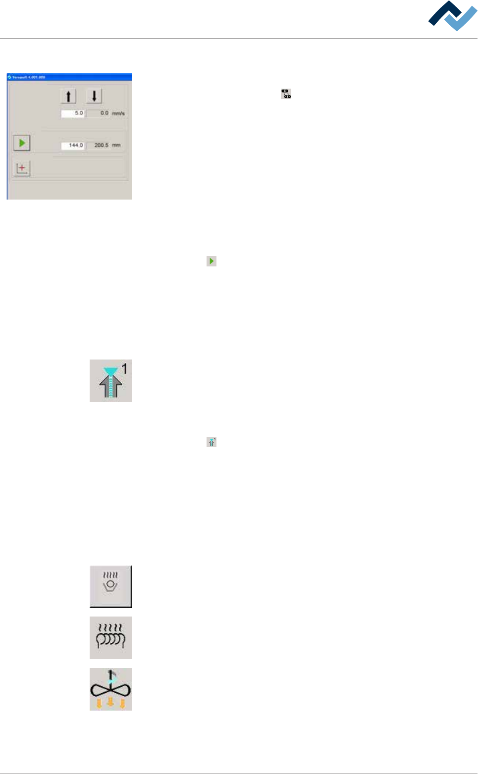
5.3.10.2 Checking width adjustment
Conveyor width adjustment
Positioning
Set value Actual value
Set value Actual value
Step mode
Special positions
v
ü To check width adjustment, proceed as follows:
a) In the start dialog, click on the
button: the [Conveyor width adjustment] in-
put dialog appears.
b) [Set value] Enter the speed value of [5mm/s].
ð At this speed, the width adjustment is moved during positioning.
c) [Actual value] Display of the current positioning speed of width adjustment in
[mm/s].
ü Proceed to manually move the width adjustment on a defined set value:
a) In the [Positioning] frame, click on the [Set value] input field, to enter a set
value.
ð The conveyor is set with this width.
b) [Actual value] Display of the current conveyor width in [mm].
c) Click on the
button to start manual positioning. When an adjustment is be-
ing carried out, the button is displayed in yellow.
d) Measure the actual distance between the two conveyor rails and compare the
result with the displayed actual value. If the measured value does not match
the displayed value, width adjustment must be calibrated.
5.3.10.3 Check fluxer module
ü To monitor the fluxer module, proceed as follows:
a) Click on the symbol of the fluxer module in the start dialog.
ð The [Flux unit 1] input dialog is opened.
b) In the [Spray heads] frame, click on the [Set value] input field and enter a value
into the [%] of the maximum pump power.
c) Click on the
button.
ð The fluxer is switched on and sprays the flux. When the fluxer is switched
on, this button is displayed in yellow.
d) Switch off the fluxer.
e) Repeat the procedure with all available spray heads.
ð The process has now been completed.
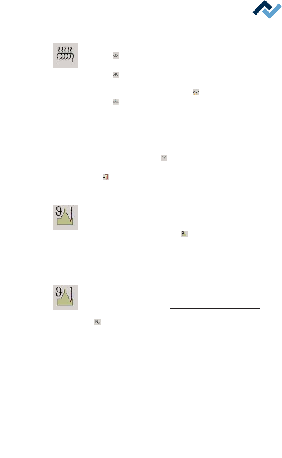
5.3.10.4 Checking preheater modules
ü To check preheater modules, proceed as follows:
a) Click on the icons of all preheater modules successively, and enter temperature
set values into their input dialogs.
b) Switch on the preheater modules. Proceed by comparing the actual values with
the set target values.
ð With the heating system switched on, the icons are displayed in yellow. In
case pf convection preheater modules, the convection system is also
turned on. The corresponding icons are shown in yellow.
Ersa GmbH Operating Instructions_VF335_en|Rev. 14|30/11/2017 105/695
5|Commissioning
5.3.10.5 Check the compressed air heater (optional)
ü To check the compressed air heater, proceed as follows:
a) Click on
under [Soldering module] in the start dialog.
ð The [Heating] input dialog (top) appears.
b) Click on
under [Heating].
ð The heater is turned on, the button is displayed in yellow. At the same
time, under [Convection], also button
is shown in yellow.
c) Click on
under [Convection].
ð The [Increase convection] is turned on and the button is displayed in yel-
low.
d) Under [Heating], enter a set value in the [Temperature] input field.
e) Compare the actual value with the entered set value.
ð The actual value has to change.
f) In the heater frame, click on
.
ð The heater and convection are turned off.
Click on
to close the dialog.
5.3.10.6 Checking the solder temperature
ü To check the solder temperature, proceed as follows:
a) Click on the symbol of the soldering module and enter a temperature set value
in the [Solder pot] input dialog.
b) Turn on the pot heater by clicking on
. In this respect, compare the actual
values with the entered set values.
ð When the heater is on, the symbol is displayed in yellow. After consider-
able time, the displayed actual temperature value must change.
5.3.10.7 Enabling the nitrogen supply
ü To enable the nitrogen supply, proceed as follows:
a) Adjust the correct pressure of the nitrogen supply on the maintenance unit. On
this regard, please read Chapter Protective gas technology (nitrogen) [
}26].
b) Click on the soldering module symbol and, under [Switch functions], click on
[
] to enable the nitrogen supply.
ð When the nitrogen supply is enabled, the symbol is displayed in yellow.
Ersa GmbH Operating Instructions_VF335_en|Rev. 14|30/11/2017 106/695