Operating Instructions_VF335_en.pdf - 第495页
9|Spare and wear parts Excentric solder pot positioning system, y-variable, view [W] 1 Fig.221: EM113-23-00c Pos Description Item number A B 1 Energy chain 139290 x Ersa GmbH Operating Instructions_VF335_en|Rev. 14…
9|Spare and wear parts
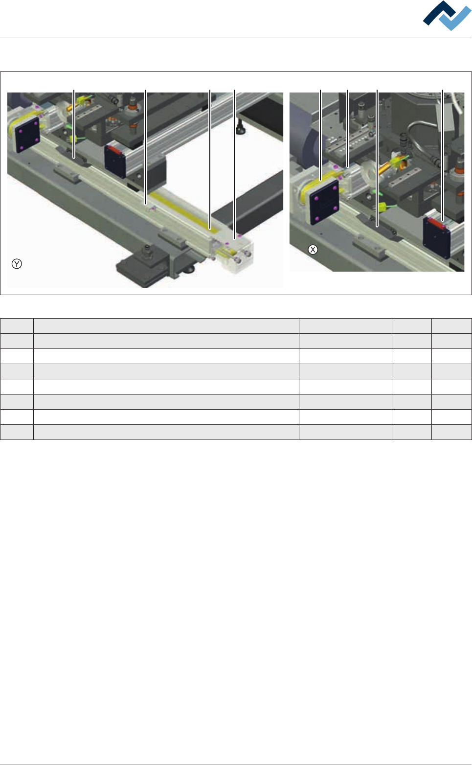
Excentric solder pot positioning system, y-variable, view [X], [Y]
1 567 72 3 4
Fig.220: EM113-23-00b
Pos Description Item number A B
1 Tooth belt 25AT10HPF; 2400 mm 175810 x
2 Tooth belt 25AT10HPF; 2440 mm 216456 x
3 Steel band 38 mm x 1167 mm 175813 x
4 Steel band 38 mm x 1100 mm 175814 x
5 Wearing part package steel band deflection 175815 x
6 Assembly set limit switch 175818 x
7 Cam set 175819 x
Ersa GmbH Operating Instructions_VF335_en|Rev. 14|30/11/2017 494/695
9|Spare and wear parts
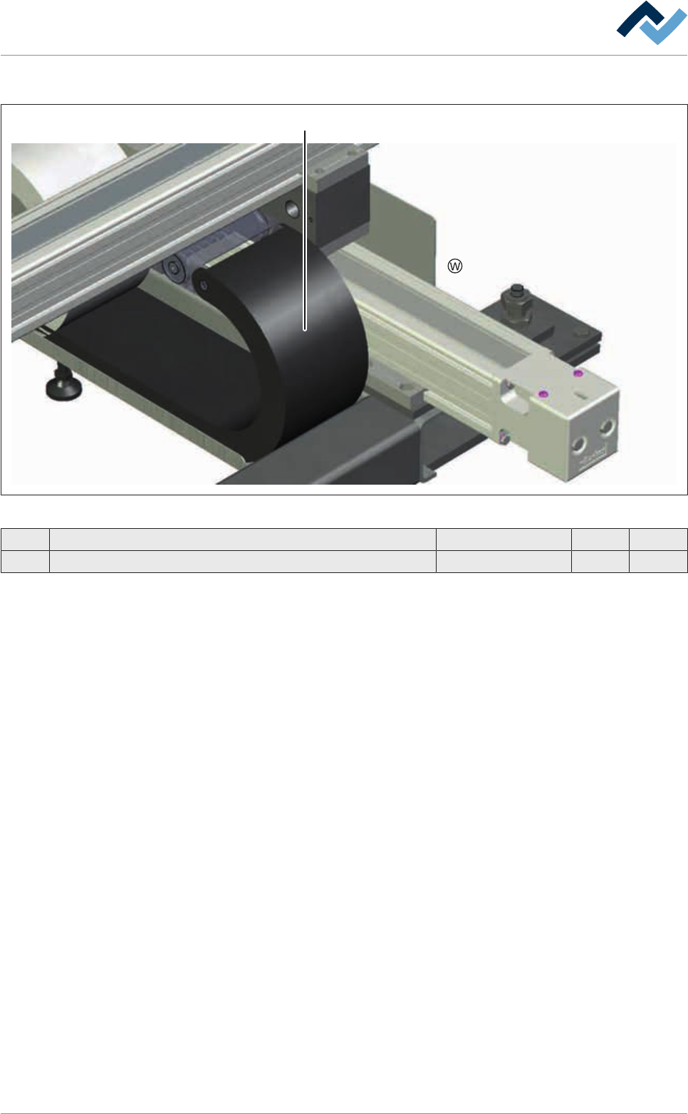
Excentric solder pot positioning system, y-variable, view [W]
1
Fig.221: EM113-23-00c
Pos Description Item number A B
1 Energy chain 139290 x
Ersa GmbH Operating Instructions_VF335_en|Rev. 14|30/11/2017 495/695
9|Spare and wear parts
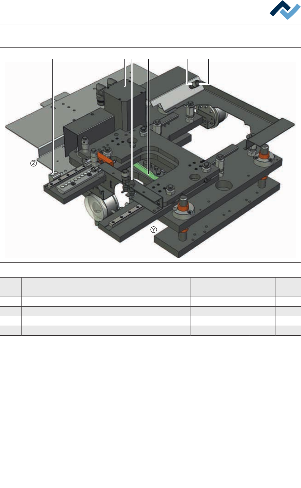
9.4.9 Z-axis excenter solder pot, y-variable
1 2 443 5
Fig.222: EM113-23-01-00
Pos Description Item number A B
1 Fixing block 190486 x
2 Tooth belt 425-5M-15 6ZR0425-5M-15 x
3 Servo drive with resolver 23567 x
4 Connector, M10 x 1 182134 x
5 Coupling M10 x 1 182135 x
Ersa GmbH Operating Instructions_VF335_en|Rev. 14|30/11/2017 496/695