Operating Instructions_VF335_en.pdf - 第312页
8|Service and maintenance Assembling the nozzle and the upper part of the gassing cap 3 2 2 1 Fig.92: Assembling the nozzle and the upper part of the gassing cap ü To assemble the nozzle and the upper part of the gass…
8|Service and maintenance
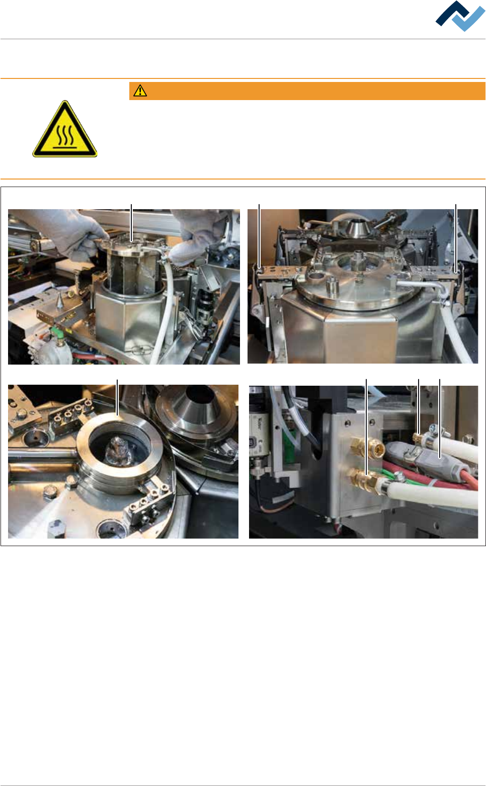
Positioning and closing the solder pot cover
WARNING
Risk of burns when dipping the components into the liquid solder!
ü When dipping the cold components, there is a risk of burns due to splashing
solder!
a) Dip parts very slowly into the solder!
b) Let the parts rest for a few minutes before closing the cover.
3
2 21
45 6
Fig.91: Positioning and closing the solder pot cover
ü To position and close the solder pot cover:
a) Lift the solder pot cover (1) and very slowly dip it into the molten mass.
b) Wait a few minutes until the solder has reached the set temperature again.
c) Close the toggle-type fasteners (2).
d) Position and fix the gassing hood.
e) Connect the quick coupling again.
ð If the solder pot is equipped with a nitrogen heating:
f) Connect the plug connector (6).
ð The process has now been completed.
Ersa GmbH Operating Instructions_VF335_en|Rev. 14|30/11/2017 311/695
8|Service and maintenance
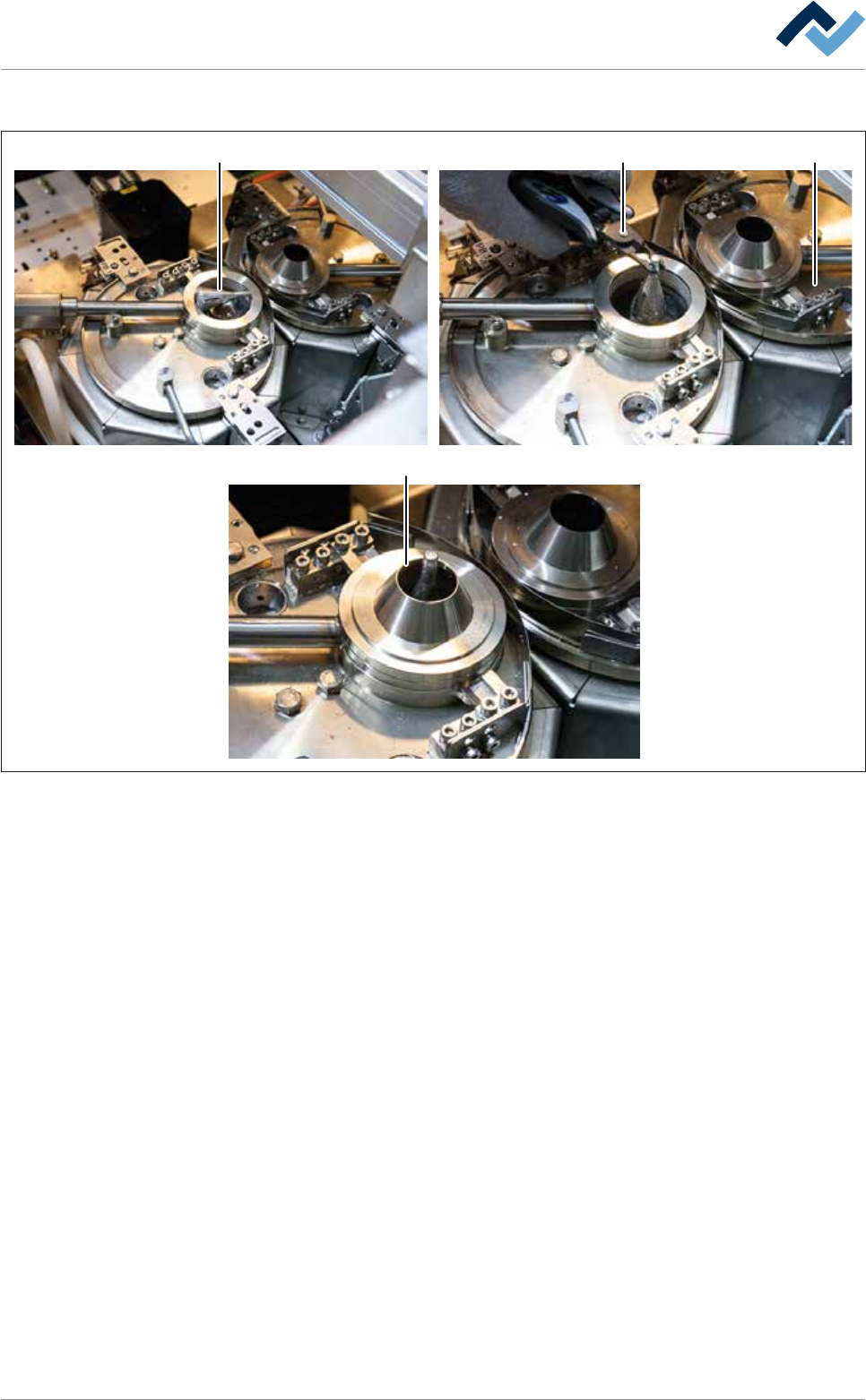
Assembling the nozzle and the upper part of the gassing cap
3
2 2
1
Fig.92: Assembling the nozzle and the upper part of the gassing cap
ü To assemble the nozzle and the upper part of the gassing cap:
a) enable the solder wave on the terminal.
b) Take the solder nozzle with the nozzle pliers, and gently lay it on the solder
wave in such a way that it is washed around by the liquid solder (1).
c) Wait a few minutes until the solder nozzle has heated up.
d) Take the solder nozzle with the nozzle pliers and carefully mount it.
ð If the solder nozzle cannot be mounted, it is not sufficiently heated.
e) Put the nozzle back on the solder wave and wait until the nozzle is sufficiently
heated.
f) Mount the solder nozzle.
g) Mount the upper part (3) on the gassing cap.
h) Close all hoods and doors.
i) Stop the service module.
ð The process has now been completed.
Ersa GmbH Operating Instructions_VF335_en|Rev. 14|30/11/2017 312/695
8|Service and maintenance
8.5 Maintenance work to be performed daily
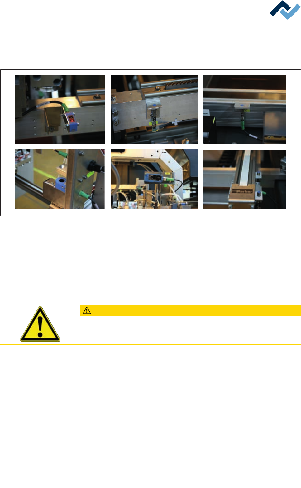
8.5.1 Sensors: visual inspection
Fig.93: Visually inspecting sensors
Visually inspecting sensors
ü To visually inspect all available sensors:
a) Clean dirty sensors using a soft cloth. No dirt should be visible.
b) Have a certified electrician replace faulty sensors.
ð The process has now been completed.
With regard to this, please refer to the Cleaning agents used [
}300] Chapter.
CAUTION
Material damage is possible!
Do not clean plastic surfaces with solvents!
Also see
2 Cleaning agents used [}300]
Ersa GmbH Operating Instructions_VF335_en|Rev. 14|30/11/2017 313/695