Operating Instructions_VF335_en.pdf - 第172页
6|Function description 6.9.5 The setting options in the [General soldering program data] The central part of the [General soldering program data] dialog is divided into sev- eral registers (columns). Each register repr…

6|Function description
6.9.4 The [Soldering program data] dialog
In this dialog, you can easily get a general idea of the soldering program, and enter
an explanatory info text. In additiosn, you can set the conveyor width if the ma-
chine features a position monitoring function controlled by the soldering program.
Entering a program name
ü To enter a program name:
a) You can enter a name for the soldering program in the [Program name] input
field.
ð This is only possible if the soldering program is recreated. If an existing pro-
gram is processed, this input field has already been assigned and cannot be ed-
ited.
Info text for the soldering program
ü To enter an info text:
a) Enter an explanatory text for the soldering program in the [Infotext:] input
field.
Which user last saved the soldering program?
ü [Last modification by:]
a) Here you can see which user last saved the soldering program.
Which version was last saved?
ü [Version:]
a) Here you can see which version was last saved. After each storing process this
number is incremented.
Recalculating all process times
ü To recalculate process times:
a) Click on [Process time].
ð All process times that are relevant to the soldering process are recalculated by
the controller. This does not affect the transfer times of the conveyor sections.
If you have manually adjusted individual process times in the soldering pro-
gram, these times will be overwritten again by clicking the corresponding but-
ton.
ü Setting the conveyor widths:1
a) Enter the conveyor widths for this soldering programme in the input filed [Con-
veyor width adjustment].
ð If the soldering programme is activated, the conveyor width will be preset with
this value. This option is only available if the machine features a soldering pro-
gramme-controlled positioning control.
NOTE
Why must thermal expansion be considered?
When entering the conveyor width, the thermal expansion of the PCB must be con-
sidered. The PCB can expand during processing and be clamped between the con-
veyor rails.
Ersa GmbH Operating Instructions_VF335_en|Rev. 14|30/11/2017 171/695
6|Function description
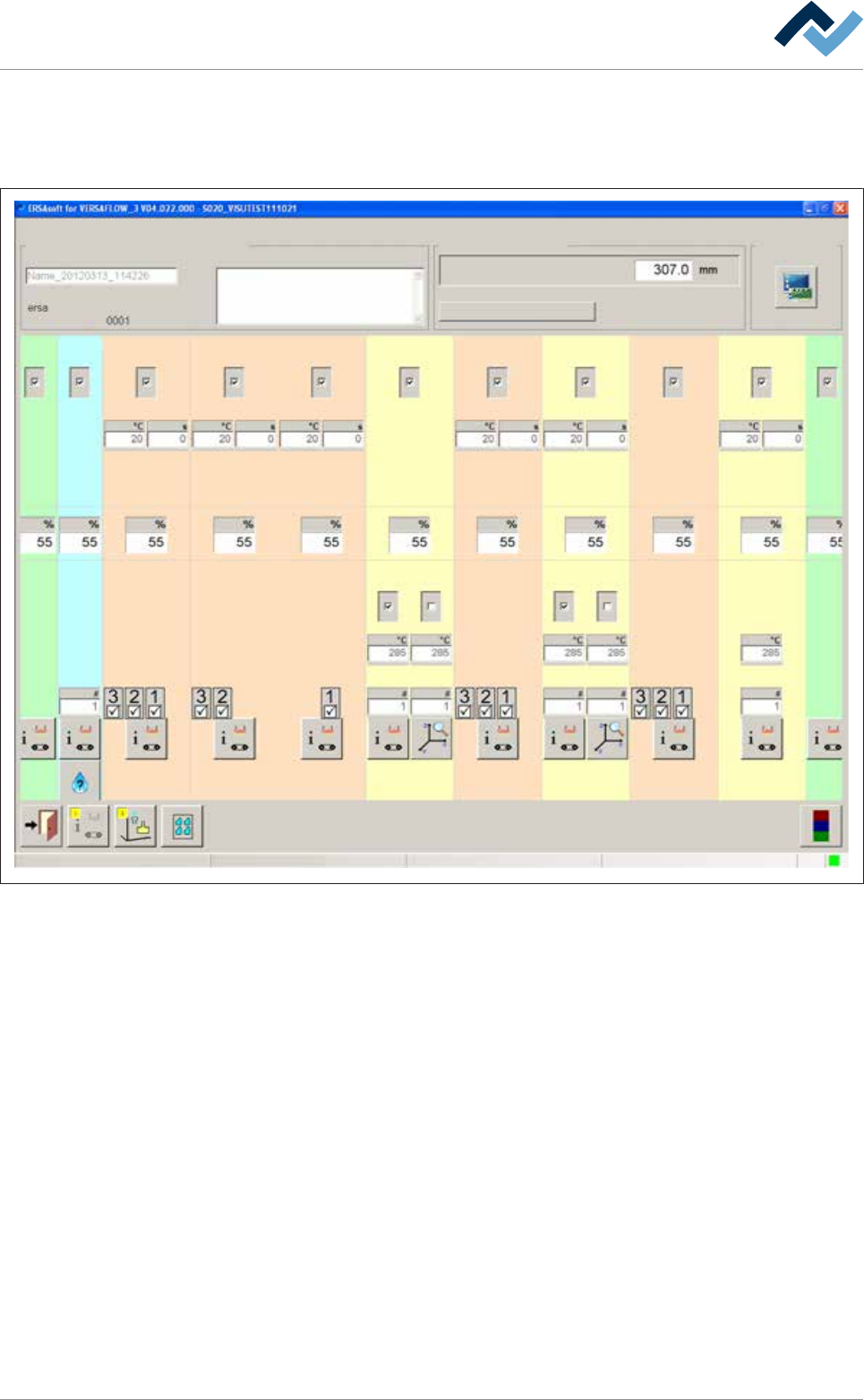
6.9.5 The setting options in the [General soldering program data]
The central part of the [General soldering program data] dialog is divided into sev-
eral registers (columns). Each register represents a module:
Infeed
user: Maintenance mode
ersa
Soldering program editor General soldering program data
Program informations
Program name
Version:
Last modification by:
Infotext:
Conveyor
Conveyor width adjustment
Graphical data
Process time
Fluxer unit Preheating Preheating Preheating Preheating PreheatingSoldering module Soldering module Soldering module Exit
Solder pot Solder pot
21 12 11 1 2 361
1 2 21
41
Change settings for a module within a register. By clicking on the button at the bot-
tom end of a register, you reach a further dialog related to the module.
Ersa GmbH Operating Instructions_VF335_en|Rev. 14|30/11/2017 172/695
6|Function description
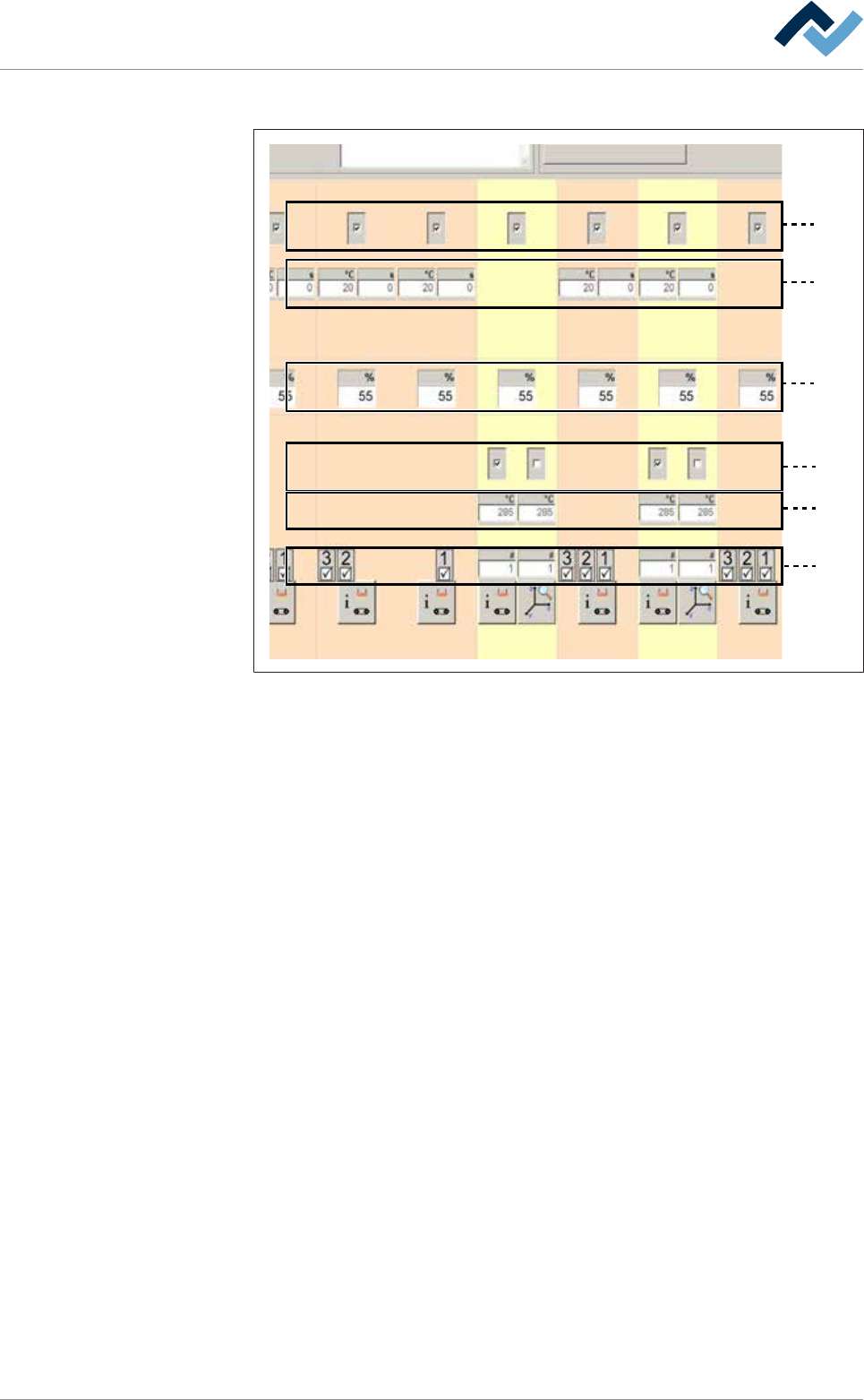
Each module features up to six levels:
1
2
3
4
5
6
Fig.36: The module levels
– Level 1: In this level, you can enable the module. When a module has been ac-
tivated, a checkmark appears.
– Level 2: Preheaters above. In this level, you can set the preheater temperat-
ures and process time.
– Level 3: Conveyor sections. In this level, you can set the conveyor speed of the
module.
– Level 4: In this level, you can enable the pot. In double pot soldering modules
(optional), you can enable one or two pots. When a pot has been enabled, a
checkmark appears.
– Level 5: Soldering temperature. In this level, you can set the soldering temper-
ature.
– Level 6: Solder nozzle number: In the case of a soldering module, you can set
the solder nozzle number in this field.
– Level 6: Spray nozzle number. In the case of a fluxer module, you can set the
spray nozzle number in this field.
– Level 6: In the case of a segmented pre-heat module, you can enable the indi-
vidual segments of the heat cartridge. When a segment has been enabled, a
checkmark appears.
6.9.6 Infeed unit settings
No settings can be entered into this dialog.
Ersa GmbH Operating Instructions_VF335_en|Rev. 14|30/11/2017 173/695