Operating Instructions_VF335_en.pdf - 第125页
6|Function description 6.3 Prevailing term definitions in this instruction manual 6.3.1 Dialogs Dialogs are windows in which you can perform settings or read values. They always fill the entire screen. They can be divi…
6|Function description
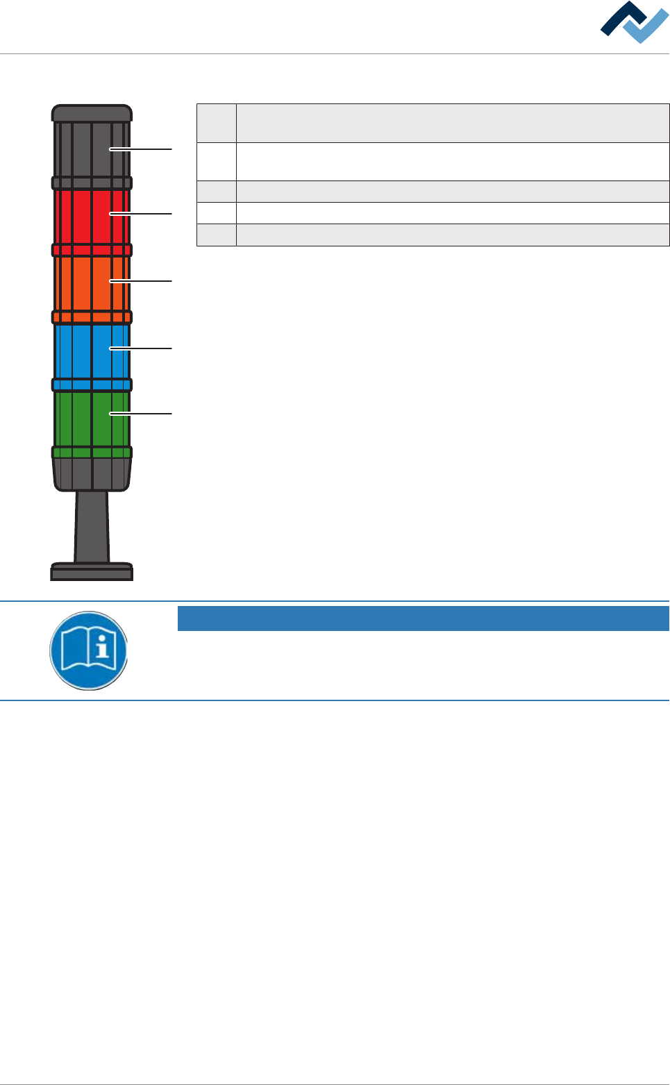
6.2.2 Signal lamp
1
2
3
4
5
1 Horn: The horn sounds when a message appears for a set period of time.
This function can be disabled.
2 Red: Emergency; dangerous condition, abnormal condition, imminent crit-
ical condition.
3 Orange: Abnormal condition; imminent critical condition.
4 Blue: Mandatory; operator intervention required.
5 Green: Normal condition; wait.
NOTE
Supplementary documents
With respect to this, please also read the document [120062] on the data carrier
[product_data_selective], which is included in the delivery.
Ersa GmbH Operating Instructions_VF335_en|Rev. 14|30/11/2017 124/695
6|Function description
6.3 Prevailing term definitions in this instruction manual
6.3.1 Dialogs
Dialogs are windows in which you can perform settings or read values. They always
fill the entire screen. They can be divided into:
– Start dialog
– Input dialogs
– Setting dialogs
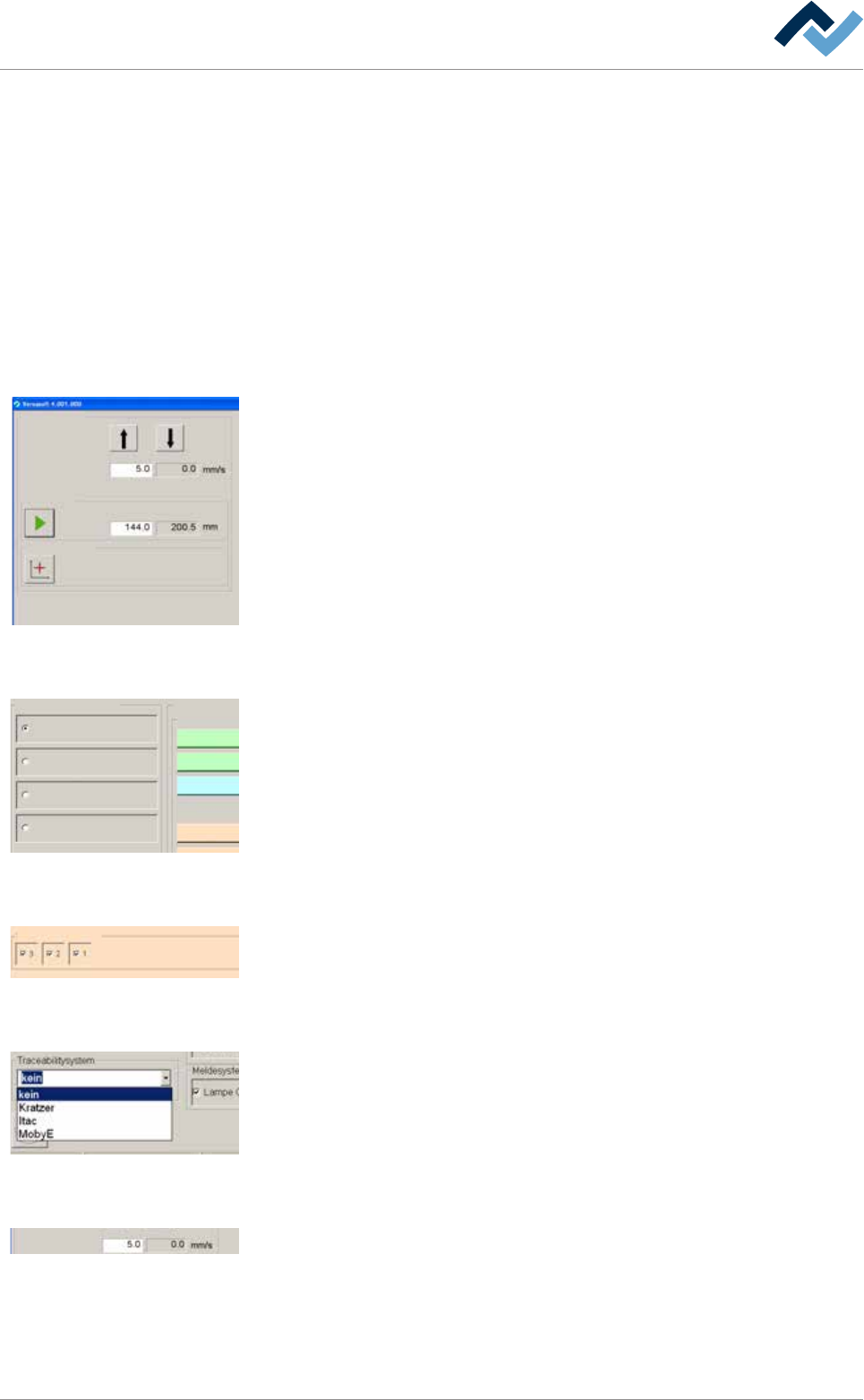
6.3.2 Frames
Conveyor width adjustment
Positioning
Set value Actual value
Set value Actual value
Step mode
Special positions
v
Frames are always visibile inside the dialogs. They summarize elements connected
together in a group. The example shown, the input and display fields as well as the
buttons for width adjustment are summarized in a frame.
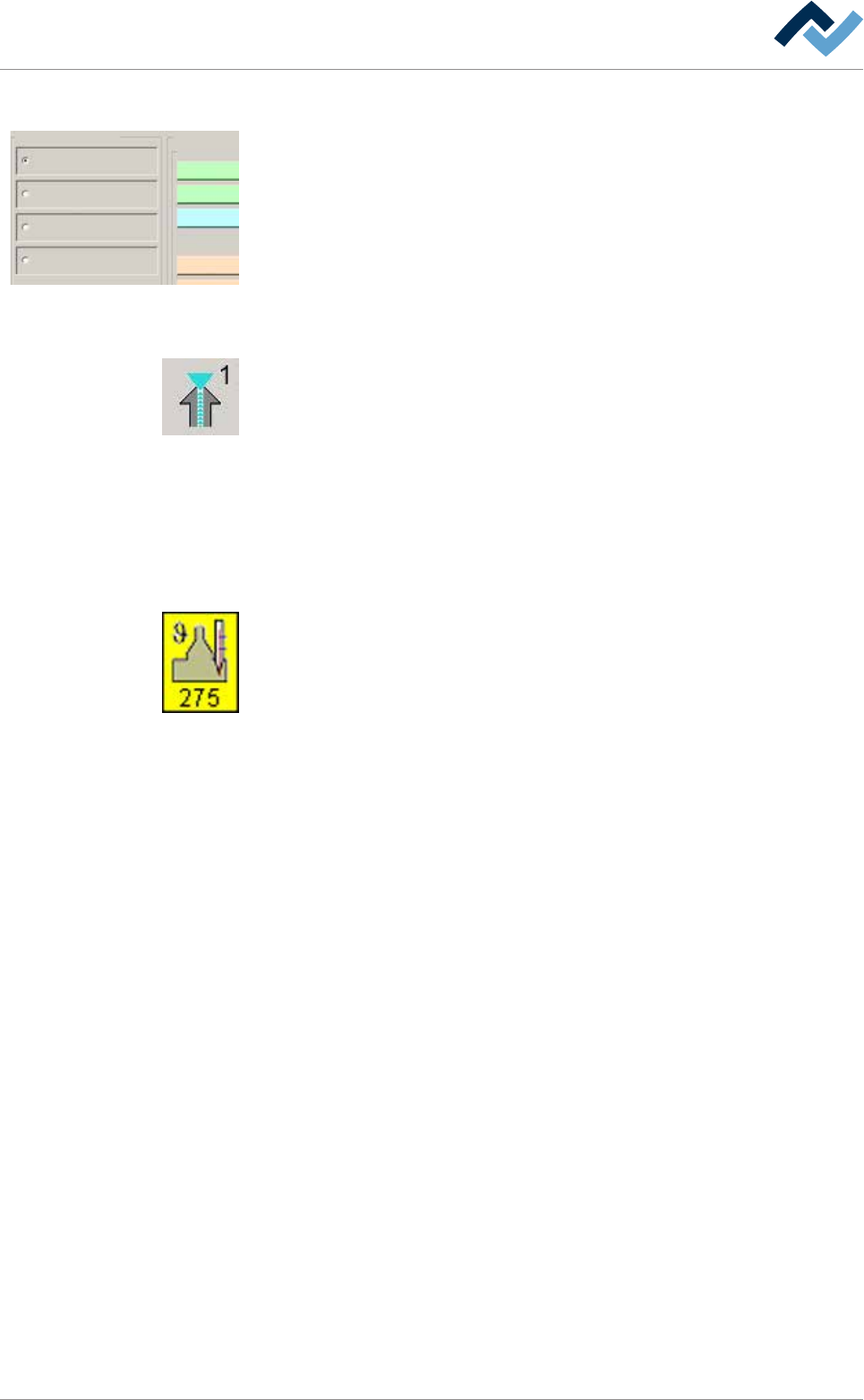
6.3.3 Radio button
Profile
User administration
Logging
File path
General settings
Settings
User maintenance mode
Preheating
Soldering module
Exit
Default
11
1
Radio buttons are circular and always appear in groups. They can be enabled but
exclude each other. They can only be enabled individually.
6.3.4 Checkbox
Edit dialog Preheating
Heating
power value
Temperature
Sections
user: none maintenance mode
manual
power valuecurrent
Set value Actual value
A checkbox can be enabled by clicking on it. If the checkbox is enabled, a check-
mark appears. As a result, the associated function is enabled.
6.3.5 Dropdown menu
A dropdown menu contains several entries each of which can be individually selec-
ted by clicking on the small triangle on the right. The selected entry is always dis-
played in blue.
6.3.6 Input fields and display fields
Conveyor width adjustment
Positioning
Set value Actual value
Set value Actual value
Step mode
Special positions
v
Input fields always have a white background. Usually, a numerical table for entering
values opens up when these fields are clicked on.
Display fields are always displayed in colour or have a grey background. You cannot
change but only read the assigned values.
Ersa GmbH Operating Instructions_VF335_en|Rev. 14|30/11/2017 125/695
6|Function description
6.3.7 Function and dialog descriptions
Profile
User administration
Logging
File path
General settings
Settings
User maintenance mode
Preheating
Soldering module
Exit
Default
11
1
Function and dialog descriptions are always written in squared brackets; e.g.:
– [Profile]
– [User administration]
– [File path]
– [Logging]
6.3.8 Buttons
Buttons are usually square and, with a few exceptions, contain icons or text indicat-
ing their functions. Buttons may have the following functions:
– Modules are enabled or disabled with a click on their respective buttons. If a
module is enabled, its respective button is displayed in yellow.
– Dialogs can be opened or closed by clicking on the corresponding buttons.
– Other functions are carried out.
This instruction manual will always describe the functions of a button first.
6.3.9 Symbols
Symbols are rectangular. They only appear in the start dialog and contain icons in-
dicating their function, in this example a soldering module. Symbols have two func-
tions:
– Dialogs can be opened with a click on the symbols.
– Inside the symbols, actual values such as the current solder temperature can
be displayed.
6.3.10 Operating instructions
the operating instructions contain:
– references to the measures to be adopted
or
– instructions to be followed by all means.
The operating instructions are structured as follows:
ü this symbol means: prerequisite for the implementation of a measure or
ü aim of a measure.
a) This symbol means: description of a measure.
ð This symbol means: intermediate result.
ð This symbol means: result.
An example: pressure adjustment
ü Remove the cover panel.
a) Adjust the (A) regulator air pressure to 2.5 bar.
ð The symbol on the screen turns green.
b) Reinstall the cover panel.
ð The air pressure has been properly set.
Ersa GmbH Operating Instructions_VF335_en|Rev. 14|30/11/2017 126/695