Operating Instructions_VF335_en.pdf - 第638页
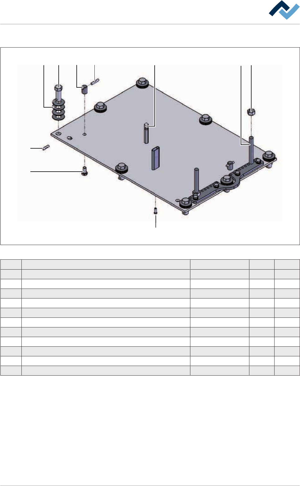
9|Spare and wear parts 9.9.1.5 DIP solder pot nozzle plate 1 2 4 10 5 7 8 3 9 3 Fig.354: Duesenplatte_DIP_VF3_01 Pos Designation Item number A B 1 Rivet 4x16 A2 92846 x 2 Bajonet cap, spring 110254 x 3 Locking bolt 10…
9|Spare and wear parts
9.9.1.4 DIP soldering unit pressure plate
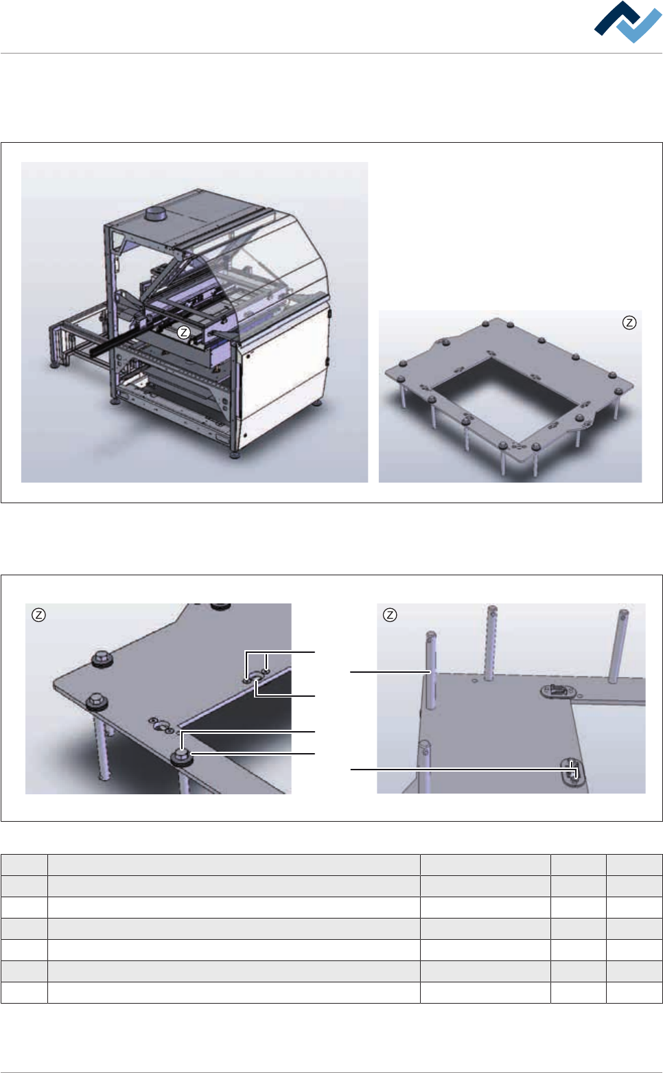
Overview
Fig.352: EMN768-0
DIP soldering unit pressure plate, view [Z]
1
2
4
5
3
6
Fig.353: EMN768-0a
Pos Designation Item number A B
1 Locking bolt 92833 x
2 Bajonet cap, spring 110254 x
3 Countersunk screw 102588 x
4 Rivet 4x16 A2 92846 x
5 Bajonet cap, bottom part 91224 x
6 Hexagonal nut 91248 x
Ersa GmbH Operating Instructions_VF335_en|Rev. 14|30/11/2017 637/695
9|Spare and wear parts
9.9.1.5 DIP solder pot nozzle plate
1
2 4
10
5 7 83
9
3
Fig.354: Duesenplatte_DIP_VF3_01
Pos Designation Item number A B
1 Rivet 4x16 A2 92846 x
2 Bajonet cap, spring 110254 x
3 Locking bolt 102036 x
4 Stoppbolzen 65 mm lang 65868 x
5 Removing bolt 121751 x
6 Rivet 4x20 A2 6KS04X20E1775 x
7 Center support bolt 121761 x
8 Nut M8, stainless steel 6M080000E0934 x
9 Nozzle fixing screw M4x10 121746 x
10 Hexagonal screw M6 6M06X010E0933 x
Curtains according to product specification See delivery note x
Ersa GmbH Operating Instructions_VF335_en|Rev. 14|30/11/2017 638/695
9|Spare and wear parts
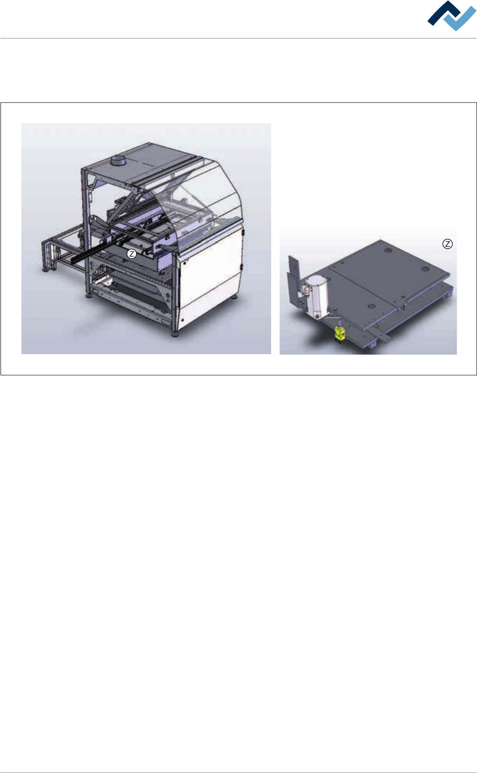
9.9.1.6 DIP soldering unit lifting system
Overview
Fig.355: EM47-22-02-00A
Ersa GmbH Operating Instructions_VF335_en|Rev. 14|30/11/2017 639/695