Operating Instructions_VF335_en.pdf - 第393页
8|Service and maintenance Cleaning the wave height measurement device NOTE Additional documents See document [278171] for wave height measuring system adjustment and setting. This document is on [product_data_selective…

8|Service and maintenance
f) If necessary, remove any contamination (oxides, dross) with a silicone brush.
Remove any stubborn solder residue with a wooden scraper.
ð The process has now been completed.
Ersa GmbH Operating Instructions_VF335_en|Rev. 14|30/11/2017 392/695
8|Service and maintenance
Cleaning the wave height measurement device
NOTE
Additional documents
See document [278171] for wave height measuring system adjustment and setting.
This document is on [product_data_selective] media.
2 2
4
7
12 12
1111
8 89 10
5 66
1
3
13
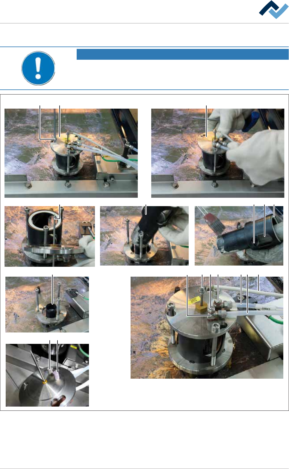
Fig.144: Cleaning the wave height measurement device
ü To clean the lid components:
ü Note: The parts coming into contact with solder are easier to clean while they
are still hot!
Ersa GmbH Operating Instructions_VF335_en|Rev. 14|30/11/2017 393/695

8|Service and maintenance
a) Loosen the three hexagonal screws (1) of the lid (2) just enough to easily rotate
the lid.
b) Turn the lid (2) clockwise and remove it.
c) Clean the probe (3) with a stainless steel brush. In doing so, do not loosen the
screw connection of the probe!
d) Clean both filter made of sintered metal (12) with a stainless steel brush.
ð In case of damage or very heavy soiling:
e) Have both filters replaced by specialist staff. In this case, have also connection
screws (13) disassembled, and clean the bores in the connection screws (11).
f) Carefully remove the lid after assembly in the maintenance tray.
ð The process has now been completed.
ü To clean the nozzle components:
a) Remove the cup (4) and clean the inside and outside.
b) Clean the sight glass (5) inside and outside.
c) Clean the nozzle (7) inside and outside.
d) Remove dross from the solder surface in the nozzle area using a solder scraper.
e) Visual inspection of the seals (6).
ð If the seals (6) are damaged:
f) Replace both seals. Carefully determine the correct installation position of the
seals!
g) Re-install the cup (4).
ð The process has now been completed.
ü To reassemble the wave height measurement:
a) Put the lid (2) on, turn anti clockwise and tighten the hexagonal screws (1)
again.
b) Visually inspect the hoses (8), the connection (9) and the line (10).
ð Firm fit must be guaranteed.
c) Visual inspection of the probe screwing.
ð If the screwing has come loose:
d) Have the probe readjusted by qualified staff.
ð Note: After assembly, have the nitrogen atmosphere in the measuring
chamber checked by qualified staff. This test must be carried out with on-
going solder wave and active nitrogen gassing.
ð The process has now been completed.
Ersa GmbH Operating Instructions_VF335_en|Rev. 14|30/11/2017 394/695