Operating Instructions_VF335_en.pdf - 第248页
6|Function description 100% wave power In a 100% wave power, the solder wave may be noisy, but not tilt to one side. With small nozzles (up to an outer diameter of about 10 mm), the solder wave forms a dome. The wave m…
6|Function description
6.15 The solder nozzle data table
To work with a solder nozzle, you must install and enable it in the [Data table
solder nozzle].
In principle, installing a solder nozzle takes place in three steps:
– Activating and inserting the nozzle into the solder nozzle data table
– Determining the offset for a wave power of 1%
– Determine gradients and offset for a wave power of 75%.
The exact procedure for installing a solder nozzle is described in Chapter Tutorial:
Installing a new solder nozzle [}255].
6.15.1 The behaviour of the solder wave with different solder nozzles
The behaviour of the solder wave is influenced by the following factors:
– Wave power
– Gradient
– Wave offset
– Test distance [mm] Solder wave height test
– Shape of the solder nozzle.
These factors must be matched to one another in such a way that the solder wave
shows the following behaviour:
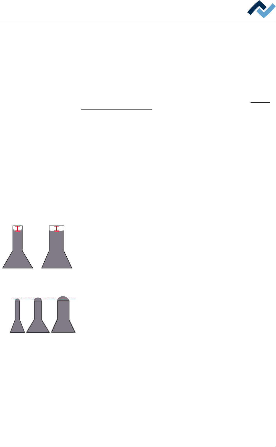
Wave power at 1% of the maximum value
4 mm
With a 1% wave power of the maximum value, the solder should be in the middle
of the nozzle, about 4 mm under the upper edge of the top. In a narrow nozzle, the
solder is drawn by capillary action upwards to the sides, while this effect is slighter
in a wide nozzle.
Wave power at 75% of the maximum value
3 mm
In a 75% wave power of the maximum value, the solder wave should lie still on the
nozzle, i.e. make no horizontal or vertical movement. It ideally has a height of
about 3 mm. The height of the solder wave is also determined by the distance of
the test needle from the upper edge of the [Test distance [mm]] solder nozzle.
With narrow nozzles (inner diameter < 3 mm), it may be useful to decrease this
value by 0.5 mm to obtain an optimal solder wave, whereas with nozzles with a
large diameter (inner diameter > 8 mm), it is useful to increase the value by 0, 5
mm.
Ersa GmbH Operating Instructions_VF335_en|Rev. 14|30/11/2017 247/695

6|Function description
100% wave power
In a 100% wave power, the solder wave may be noisy, but not tilt to one side. With
small nozzles (up to an outer diameter of about 10 mm), the solder wave forms a
dome. The wave moves horizontally and vertically.
Ersa GmbH Operating Instructions_VF335_en|Rev. 14|30/11/2017 248/695
6|Function description
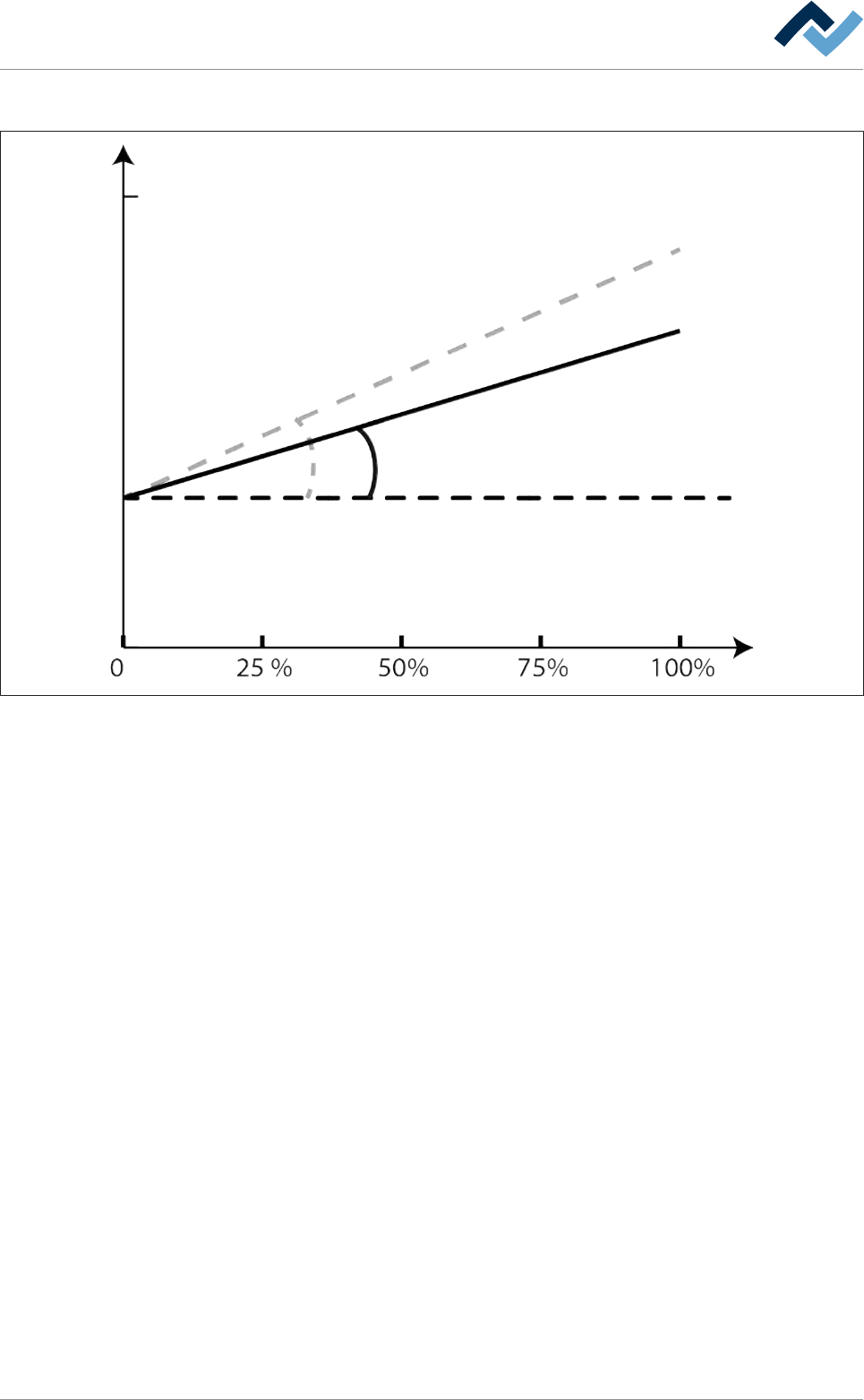
The power control results from Wave power, Gradient and Offset!
Gradient
Offset
Wave power
30000
Control
Pump
Pump
Control
Soldering nozzle
Soldering nozzle
(B)
(A)
Fig.65: Pump power control: The relationship between Wave power, Gradient and Offset.
For an optimal soldering result, different nozzles must be also operated with different con-
trol power. The black characteristic curve shows the course of the control power for nozzle
(A); the grey curve shows the course of the control power for nozzle (B).
The relationship between Wave power, Gradient and Offset can be graphically illus-
trated as shown here. Offset is the value that is required to leave the solder lying
about 4 mm below the nozzle edge with a wave power of 1%. In this case, the con-
trol power is purely a numerical value can be calculated with the following formula:
Control power = Offset + (Wave power * Gradient)
Ersa GmbH Operating Instructions_VF335_en|Rev. 14|30/11/2017 249/695