Operating Instructions_VF335_en.pdf - 第657页
9|Spare and wear parts 9.9.2.6 Solder feed with turret bar container (option) 5 1 1 4 3 2 6 Fig.372: EM140-61-50-004 Pos Description Part No. A B 1 One-way restrictor VFOH-LE-A-G18-Q4 302565 x 2 Sensorclip f. cylinder…

9|Spare and wear parts
9.9.2.5 Standard DIP soldering module (multiwave) setup verification
Item Designation Item number A B
1 Rope tool coding for down holder 322332 X
2 Rope tool coding for nozzle plate 322337 X
3 Rope tool coding for protection 322336 X
Ersa GmbH Operating Instructions_VF335_en|Rev. 14|30/11/2017 656/695
9|Spare and wear parts
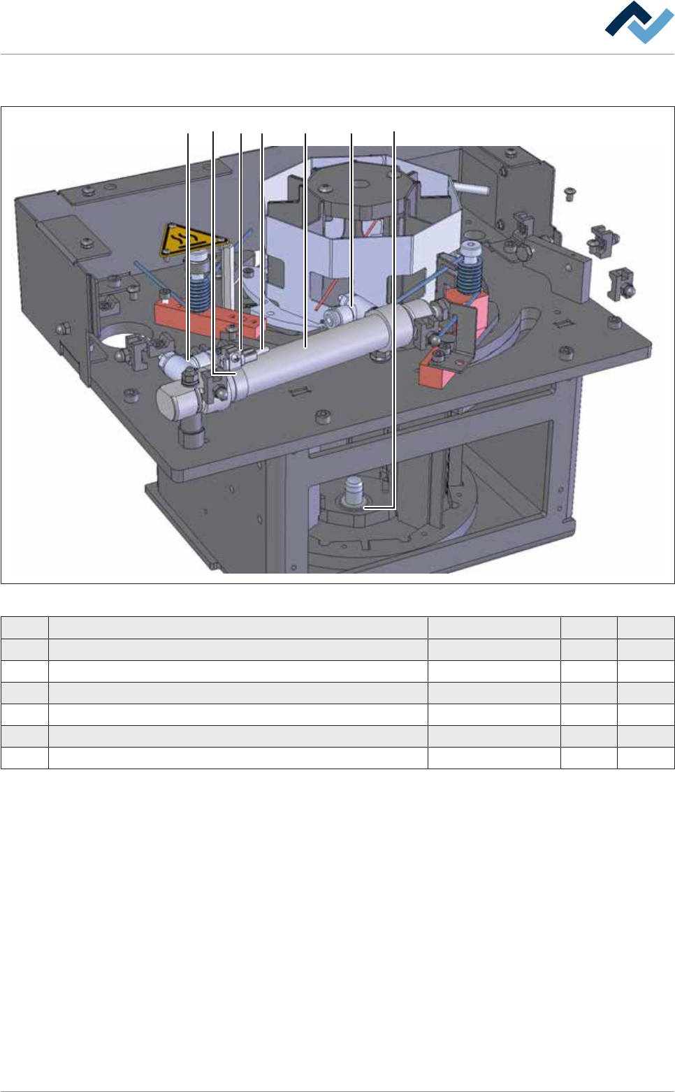
9.9.2.6 Solder feed with turret bar container (option)
5 11 432 6
Fig.372: EM140-61-50-004
Pos Description Part No. A B
1 One-way restrictor VFOH-LE-A-G18-Q4 302565 x
2 Sensorclip f. cylinder, Ø 20 208090 x
3 Mounting for sensor 208077 x
4 Insertion aid, fixed 132240 x
5 Round zylinder double-act, heat resist., Ø 20, stroke 80 312167 x
6 Plain bearing XFM-121418-059 312166 x
Ersa GmbH Operating Instructions_VF335_en|Rev. 14|30/11/2017 657/695
9|Spare and wear parts
2 111
3
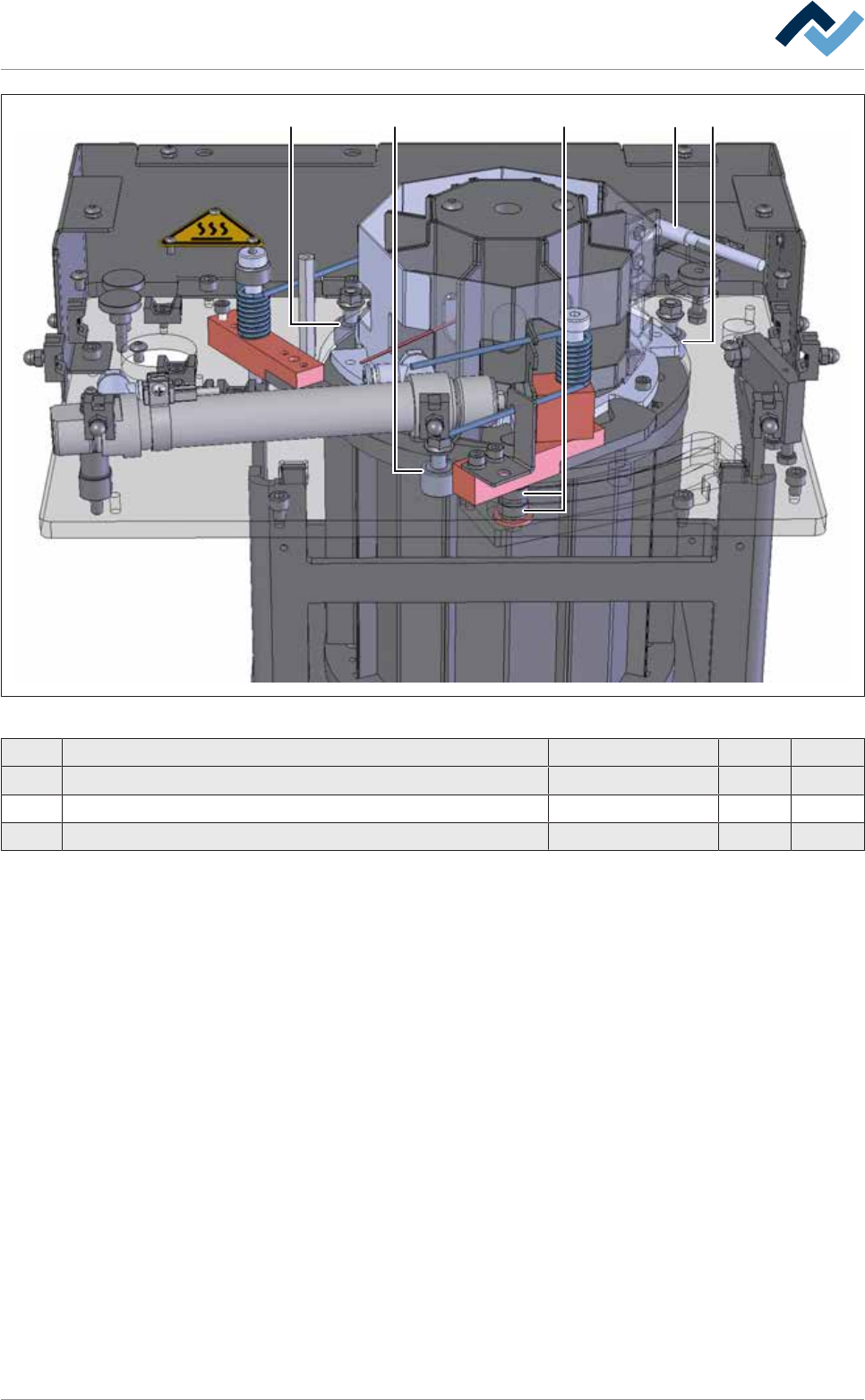
Fig.373: EM140-61-50-00b
Pos A B
1 Curved Roller Ø=16, w=11, M6 6LAKR16 x
2 Bearing 628/6-2Z up to 90 °C 6LA628-6-2Z x
3 Fiber Optic Cable Reflex 161-238-204E40 207006 x
Ersa GmbH Operating Instructions_VF335_en|Rev. 14|30/11/2017 658/695