Operating Instructions_VF335_en.pdf - 第397页
8|Service and maintenance Assembling the nozzle plate A A X 1 2 3 4 5 11 6 7 8 9 10 12 13 14 15 16 17 18 1 X B C B D Fig.147: Assemble the nozzle plate. Always grasp locked extraction tools by the top handle (A)! ü To…
8|Service and maintenance
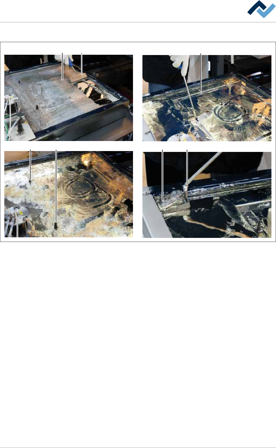
Cleaning the solder surface
4
5 5
67
1
2
Fig.146: Cleaning the solder surface
ü To clean the solder surface:
a) Remove dross from the entire solder surface (1) using a solder scraper (2) or a
silicone scraper.
b) Collect the dross in a corner of the solder pot.
ð Note: Work carefully exerting little pressure so as not to damage the
coated surfaces!
c) Carefully clean the area around the encoding pins (5).
d) Carefully clean the contact points of the encoding pins and pressure chamber.
ð Note: This cleaning process is particularly important. The area around the
contact points must be free of oxides and dross. After installing the nozzle
plate, adhering dirt can lead to leaks!
e) Remove the dross (7) with a perforated ladle (6).
f) If necessary, refill some solder so as to obtain the original solder level again.
ð The process has now been completed.
Ersa GmbH Operating Instructions_VF335_en|Rev. 14|30/11/2017 396/695
8|Service and maintenance
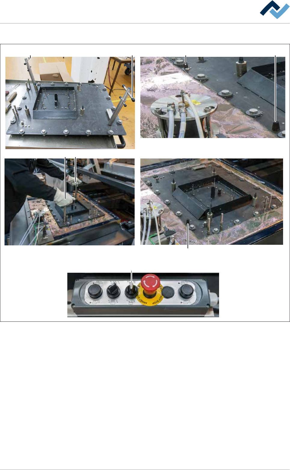
Assembling the nozzle plate
A A X
1
2
3
4
5
11
6
7
8
9
10
12
13
14
15
16
17
18
1
X
B
C
B
D
Fig.147: Assemble the nozzle plate. Always grasp locked extraction tools by the top handle (A)!
ü To assemble the nozzle plate:
ü Both extraction tools are fitted and secured to the nozzle plate.
ü The upper edge of the pressure chamber is completely covered with solder and
free of oxides and dross.
ü All bayonet locks are aligned in such a way that the slots of the screws run par-
allel to the edges of the nozzle plate.
a) Accident risk! Check the firm seating of the locks again!
b) Lift the nozzle plate with both hands by the top handles (A) .
ð Accident risk! Always grasp locked extraction tools by the top handle (A)!
c) Place the nozzle plate very slowly onto the solder surface and position it gently
via the coding keys (X).
ð If the machine has the [setup verification] option:
d) Insert the RFID chips in the chip reader.
Ersa GmbH Operating Instructions_VF335_en|Rev. 14|30/11/2017 397/695

8|Service and maintenance
e) Sequentially move the screws of the bayonet locks with appropriate tools. In
doing so, slightly press the nozzle plate down.
ð In this way, the nozzle plate is fully lowered onto the pressure chamber.
f) Turn the rotary switch (D) on the control panel to the right.
ð In this way, the solder wave is enabled. Do not run the pump without ni-
trogen gassing for an unnecessarily long time. Otherwise, a lot of dross is
produced unnecessarily.
g) Wait about 10 minutes for the nozzle plate to heat up and the solder to reach
its target temperature again.
h) Remove any extraction tools.
i) Secure the nozzle plate with the socket spanner according to the diagram
shown.
j) Start by fixing the nozzle plate always at the zero point (C) and proceed accord-
ing to the illustrated numbering.
k) Clean all inlet bores with a round brush.
l) Solder wave height visual inspection:
ð Nozzles must be uniformly filled with solder and wave height be the same
for each nozzle.
ð The process has now been completed.
Ersa GmbH Operating Instructions_VF335_en|Rev. 14|30/11/2017 398/695