Operating Instructions_VF335_en.pdf - 第421页
8|Service and maintenance 8.11.9.1 Preparation for solder pot replacement NOTE Let the solder cool off before replacing the DIP solder pot Let the solder cool off before replacing the DIP solder pot. To do so, it must …
8|Service and maintenance
NOTE
Use suitable protective equipment!
When performing any work on a hot pot, protective clothing must be worn:
a) Safety shoes
b) Face protection
c) Heat resistant gloves
d) Heat resistant apron
WARNING
Death or severe injuries are possible with extended soldering module!
ü If the soldering module is on the replacement rack while it is hot:
a) Shut off the work area with a red and white safety chain and a warning sign.
b) Remove possible tripping areas!
Replacing the DIP solder pot
The procedure for replacing the DIP solder pot takes about 30 minutes (if the DIP
solder pot has cooled down to the set temperature and if the DIP solder pot has
been heated in the heating station and has reached the set temperature). The pro-
cedure involves the following seven steps:
– Preparation for solder pot replacement
– Mounting the traction aid on the machine
– Operating the lifting cart with the replacement rack
– Connecting the cold solder pot to the (optional) heating station and preheating
it
– Removing the cooled DIP solder pot from the machine
– Inserting the (optionally pre-heated) DIP solder pot into the machine
– Replacing solder in the automatic solder feeder (optional)
– Completing the DIP solder pot replacement process
Ersa GmbH Operating Instructions_VF335_en|Rev. 14|30/11/2017 420/695

8|Service and maintenance
8.11.9.1 Preparation for solder pot replacement
NOTE
Let the solder cool off before replacing the DIP solder pot
Let the solder cool off before replacing the DIP solder pot. To do so, it must be solidi-
fied. A safety switch prevents the extraction of the DIP solder pot in case the solder is
still too fluid or too hot.
ü Cool down the DIP solder pot to the necessary set temperature.
ü The machine is in the [Maintenance mode].
a) Open the start dialog.
b) Open the input dialog for the DIP soldering module.
c) Click on the button
.
ð The DIP soldering module is moved to the [Service] position.
d) Now, if necessary, remove the nozzle plate of the DIP soldering module. For
more information, please also read the relevant chapter DIP soldering module
(multiwave) with induction pump: Clean the solder pot [}386].
ð Use the support provided.
ð After removing the nozzle plate, and before replacing the solder pot, insert
the solder pot into the machine, as described.
e) In the [Solder pot], click on the button
to switch off the heating.
ð The button is then displayed in grey.
ð The heating is switched off, and the solder will slowly cool down.
f) To avoid any unnecessary delay in the solder pot replacement procedure,
check whether the cold solder pot is already connected to the optional heating
station, and whether it is preheated so that it can reach the required set tem-
perature. For more information, please also read the relevant chapter Connect-
ing the cold solder pot to the (optional) heating station and preheating it
[}425].
g) If the machine has the [Hold Down] option, remove the [Hold Down].
h) If the machine has the [Solderbar feeder] option, remove the [Solderbar
feeder] and place it in the storage compartment on the corresponding DIP
solder pot.
i) Wait until the solder of the DIP solder pot has cooled down to the required set
temperature.
ð The process has now been completed.
Ersa GmbH Operating Instructions_VF335_en|Rev. 14|30/11/2017 421/695
8|Service and maintenance
8.11.9.2 Mounting the traction aid on the machine
1 23
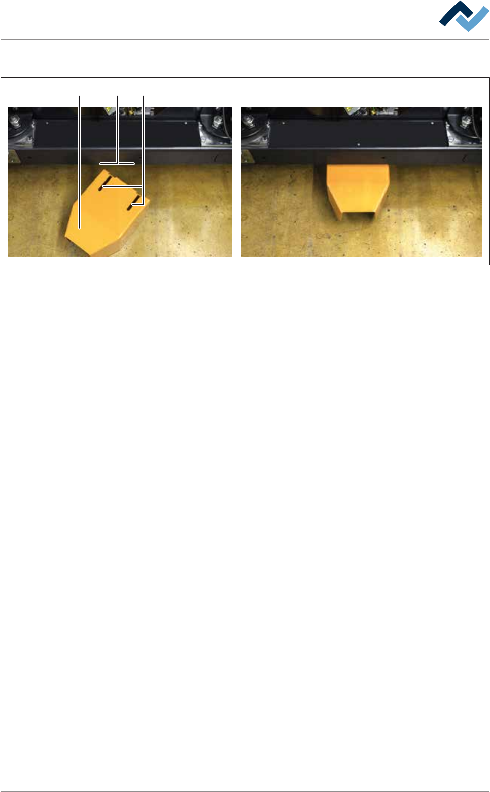
Fig.160: Mounting the traction aid on the machine.
Mounting the traction aid on the machine
Before replacing the solder pot, a traction aid must be mounted on the machine.
Thanks to this device, using the lifting cart it is possible to bring the replacement
rack to the correct position for replacing the solder pot on the machine. The lifting
cart is securely bolted to the replacement rack.
a) Insert the traction aid (1) under the DIP soldering module into the holder. In-
sert the holding screws (3) into the elongated holes (2).
ð Make sure that during this procedure the traction aid is not canted.
b) Slide the traction aid (1) backwards until it stops.
ð The process has now been completed.
Ersa GmbH Operating Instructions_VF335_en|Rev. 14|30/11/2017 422/695