Operating Instructions_VF335_en.pdf - 第460页
9|Spare and wear parts Additional module 1300 DIP XL 1 2 3 3 3 3 Fig.188: EM113-15-00a Pos Designation Item number A B 1 Lever element 86699 x 2 Pressure screw (Neopren) 6GN808-M5-45 x 3 Gas spring (500 N) * 182525 x …
9|Spare and wear parts
9.2.6 Additional module 1300 DIP XL
1 2
4 3
Fig.187: EM146-00-00a
Pos Designation Item number A B
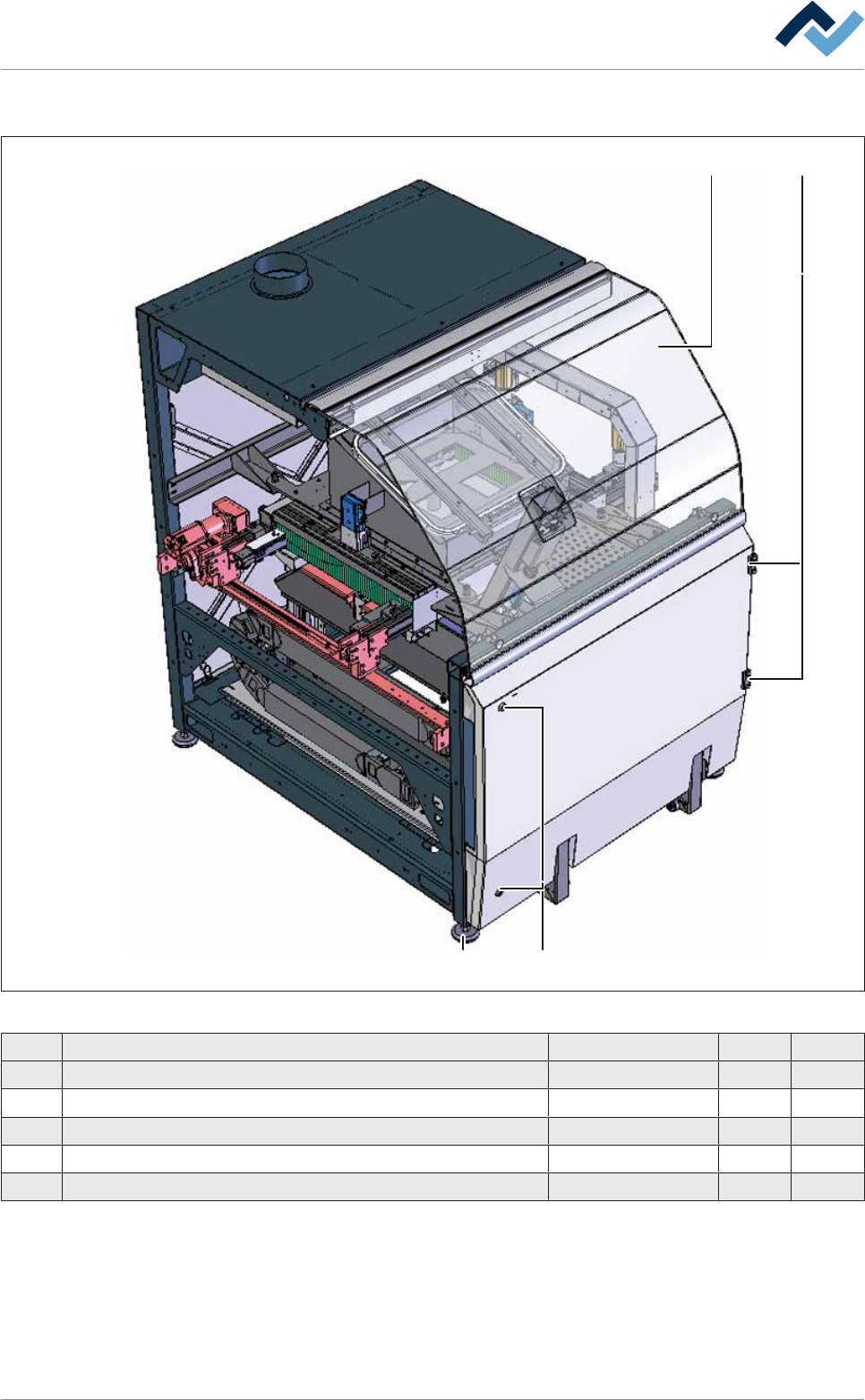
1 Safety glass plate with cutout, module 1300 261469 x
2 Hinge EMKA Type 1110-u121, right side 236505 x
3 Lock 6VER2520 x
4 Adjusting foot 6STELLFM16X155 x
5 Key for control cabinet (unpictured) 6VERSCHLÜ2531 x
Ersa GmbH Operating Instructions_VF335_en|Rev. 14|30/11/2017 459/695
9|Spare and wear parts
Additional module 1300 DIP XL
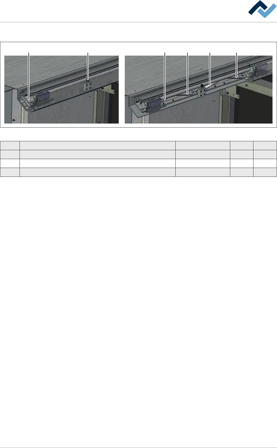
1 2 3 3 3 3
Fig.188: EM113-15-00a
Pos Designation Item number A B
1 Lever element 86699 x
2 Pressure screw (Neopren) 6GN808-M5-45 x
3 Gas spring (500 N) * 182525 x
*Please note the type designation on the gas spring housing! To mount the gas
spring, Assembly tool for gas spring, item 123716 is required! Always have gas
springs replaced by specialised personnel!
Ersa GmbH Operating Instructions_VF335_en|Rev. 14|30/11/2017 460/695
9|Spare and wear parts
9.3 Spray fluxer and options
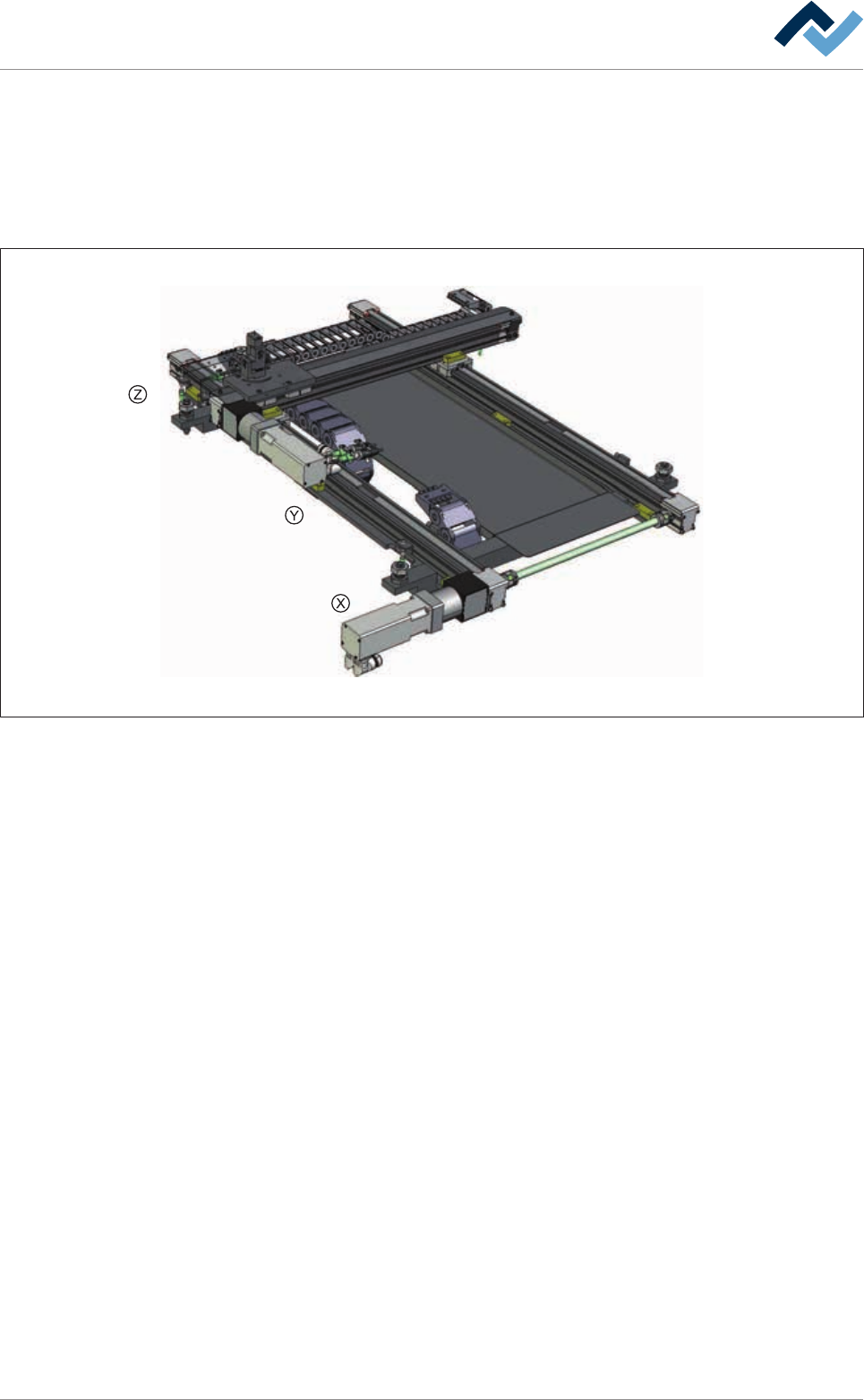
9.3.1 Complete spray fluxer
Overview
Fig.189: EM113-40-00A
Ersa GmbH Operating Instructions_VF335_en|Rev. 14|30/11/2017 461/695