Operating Instructions_VF335_en.pdf - 第176页
6|Function description In the [Congestion position] input fields, you can define a position for the nozzle, which is always approached when the machine is somewhere congested with boards. Ersa GmbH Operating Instructio…
6|Function description
user:
ersa
Soldering program editor General additional data
Program informations
Program name
Version:
Last modification by:
Infotext:
Conveyor
Conveyor width adjustment
Graphical data
Process time
Process time
Fix horizontal permanently
Park position
Congestion position
Flux unit
General additional data
Maintenance mode
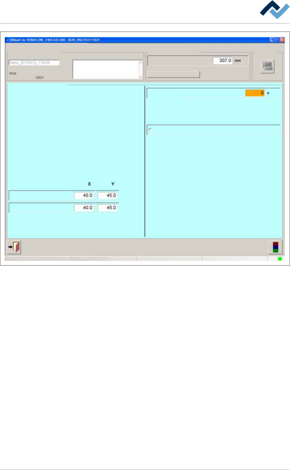
Fig.37: The [General additional data] dialog
Adjusting the process time manually
ü To adjust the process time manually:
a) Click on the [Process time] input field and enter a process time.
ð The process time is adjusted, and the time calculated by the controller for this
module is overwritten. When clicking on [Process time], the controller recalcu-
lates all process times. The process time adjusted by you is overwritten.
Permanently fixing PCBs
ü To permanently fix PCBs during processing:
a) Activate the [Fix horizontal permanently] checkbox.
ð The PCBs are aligned in the module and then laterally fixed until processing is
completed. If the checkbox is not activated, the PCBs are only aligned and then
released again. You can activate this function separately for all available fluxer
and soldering modules
Park position and jam position
In the [Park position] input fields, you can define a position for the nozzle, which is
always approached when the process step has been finished. In this position, the
module waits for the next board. You can also approach this position manually.
Ersa GmbH Operating Instructions_VF335_en|Rev. 14|30/11/2017 175/695

6|Function description
In the [Congestion position] input fields, you can define a position for the nozzle,
which is always approached when the machine is somewhere congested with
boards.
Ersa GmbH Operating Instructions_VF335_en|Rev. 14|30/11/2017 176/695
6|Function description
6.9.8 Preheater module settings
In this example, the preheater is provided with an upper compressed air heater and
dynamic light emitters, which pre-heat the board from the bottom. The bottom
preheater cassette is divided into three segments.
Enabling the module
ü To enable the module:
a) In the [General soldering program data] dialog, activate the checkbox of the
module in level 1.
ð The module has now been enabled and is used in the soldering program.
Setting preheating temperature, preheating period
ü To set the preheating temperature and period:
a) In the [General soldering program data] dialog in level 2, click on the input
fields and enter the preheating temperature in [°C] and the prehating period in
[s].
ð The PCBs will thus be subjected from above to the preheating temperature for
the duration of [Preheating time].
Setting the conveyor speed
ü To set the conveyor speed:
a) In the [General soldering program data] dialog in level 3, click on the input field
of the conveyor section.
b) Enter the conveyor speed in [%] of the maximum possible speed value.
ð This is the speed at which the board is conveyed into the next module.
Segmented pre-heat unit: Enabling segments
ü To enable the segments of the bottom preheater:
a) Enable checkboxes in the [General soldering program data] dialog in level 6.
ð If a checkbox is enabled, the segment of the heater is used in the soldering pro-
gram.
Performing extended settings in the [General additional data] dialog
ü To perform extended settings:
a) Open the [General soldering program data] dialog.
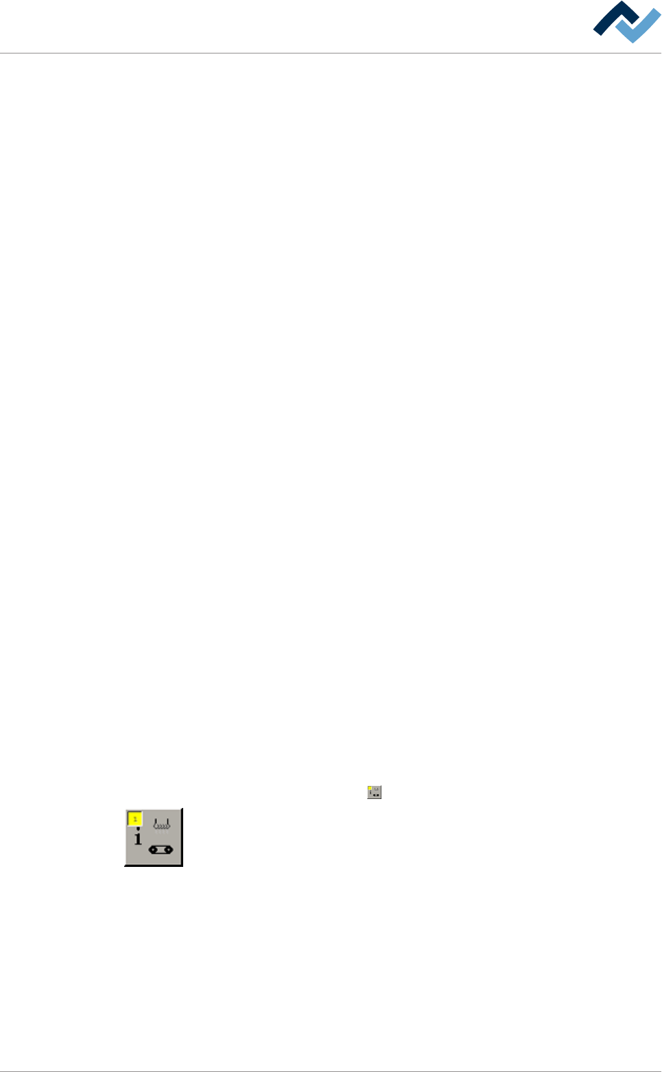
b) Below Level 6, click on the
button in the corresponding module.
Open the [General additional data] dialog. The yellow square provides information
about how often the dialog has already been opened.
Ersa GmbH Operating Instructions_VF335_en|Rev. 14|30/11/2017 177/695