Operating Instructions_VF335_en.pdf - 第246页
6|Function description NOTE To move the DIP solder pot out of the service position, acknowledge the service message To be able to move the DIP solder pot out of the service position, acknowledge the corresponding servi…
6|Function description
NOTE
Open the module doors and windows only if module maintenance has been en-
abled!
Open the module doors and windows only after module maintenance has been en-
abled and the button lights up yellow. If your machine is not provided with the op-
tional door and window interlocking system, all the doors and windows remain locked
and are only unlocked when module maintenance is enabled.
For more information, please also read the relevant chapter Door- and window in-
terlocking system (optional) [}41].
If the module does not move into the service position when Module
maintenance is enabled
Should the module not move into the set service position when module mainten-
ance is enabled, this feature must be enabled in the settings of the module before
enabling the Module maintenance :
a) In the [Soldering unit] input dialog, click on the button in the bottom toolbar
.
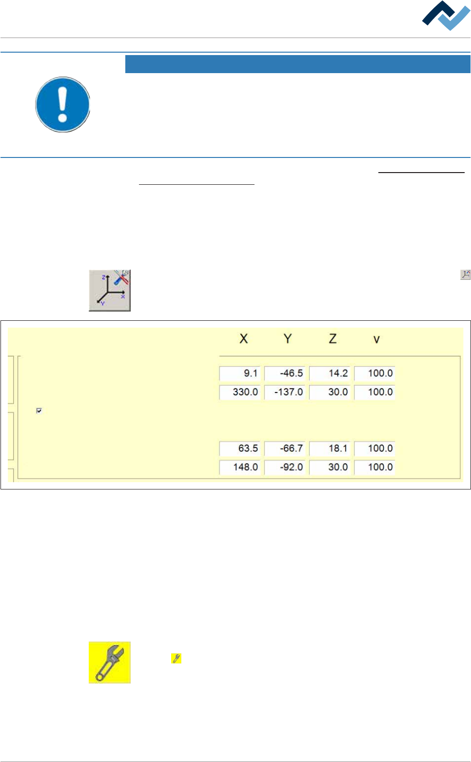
ð The [Soldering unit] input dialog is opened:
Dependence
Test
Activated for module maintenance
Positions Active tool
- -
Service
Dispence
Feeding
Abidance
Dispence
-
-
Fig.64: The [Soldering unit] input dialog
b) In the [Positions: Dependence - Active tool], enable the [Activated for module
maintenance] checkbox.
ð Now, by enabling the Module maintenance the module will move into the
service position.
ð The process has now been completed.
Exiting Module maintenance variable
ü All maintenance operations have been completed.
a) Close all the module doors and hoods.
b) In the [Soldering unit] input dialog, in the [Switch functions], click on the but-
ton
.
ð The Module maintenance is terminated.
ð The process has now been completed.
Ersa GmbH Operating Instructions_VF335_en|Rev. 14|30/11/2017 245/695

6|Function description
NOTE
To move the DIP solder pot out of the service position, acknowledge the service
message
To be able to move the DIP solder pot out of the service position, acknowledge the
corresponding service message.
Ersa GmbH Operating Instructions_VF335_en|Rev. 14|30/11/2017 246/695
6|Function description
6.15 The solder nozzle data table
To work with a solder nozzle, you must install and enable it in the [Data table
solder nozzle].
In principle, installing a solder nozzle takes place in three steps:
– Activating and inserting the nozzle into the solder nozzle data table
– Determining the offset for a wave power of 1%
– Determine gradients and offset for a wave power of 75%.
The exact procedure for installing a solder nozzle is described in Chapter Tutorial:
Installing a new solder nozzle [}255].
6.15.1 The behaviour of the solder wave with different solder nozzles
The behaviour of the solder wave is influenced by the following factors:
– Wave power
– Gradient
– Wave offset
– Test distance [mm] Solder wave height test
– Shape of the solder nozzle.
These factors must be matched to one another in such a way that the solder wave
shows the following behaviour:
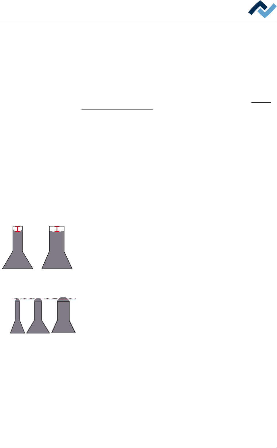
Wave power at 1% of the maximum value
4 mm
With a 1% wave power of the maximum value, the solder should be in the middle
of the nozzle, about 4 mm under the upper edge of the top. In a narrow nozzle, the
solder is drawn by capillary action upwards to the sides, while this effect is slighter
in a wide nozzle.
Wave power at 75% of the maximum value
3 mm
In a 75% wave power of the maximum value, the solder wave should lie still on the
nozzle, i.e. make no horizontal or vertical movement. It ideally has a height of
about 3 mm. The height of the solder wave is also determined by the distance of
the test needle from the upper edge of the [Test distance [mm]] solder nozzle.
With narrow nozzles (inner diameter < 3 mm), it may be useful to decrease this
value by 0.5 mm to obtain an optimal solder wave, whereas with nozzles with a
large diameter (inner diameter > 8 mm), it is useful to increase the value by 0, 5
mm.
Ersa GmbH Operating Instructions_VF335_en|Rev. 14|30/11/2017 247/695