DECAN_F2_Service(Eng_Ver1).pdf - 第107页
5-7 Head Measure the movement resistance from the 2nd section to the 5th section below the LM Guide tightening bolts. 14) Once the assembling is completed, turn on th e main switch on the front of the machine and boot th…
5-6
Fast & Flexible Chip Shooter DECAN F2 Service Manual
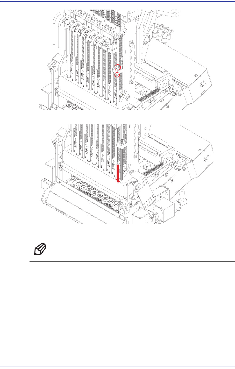
10) Remove the spline downward.
11) Replace the Ball spline with a new one.
Ref The part number of the new Ball Spline is MC13-000124.
12) Assemble the board in the reverse order of disassembling.
13) When assembling, refer to the following.
Before assembling the Ball Spline to the Head Body, be sure to check whether the
spline becomes stuck when moving it up and down.
Apply EP2 (Grease) to the inserting hole of the ball spline of the main body.
After assembling, measure the movement resistance of the Z Rod Housing and Z Top
Housing.
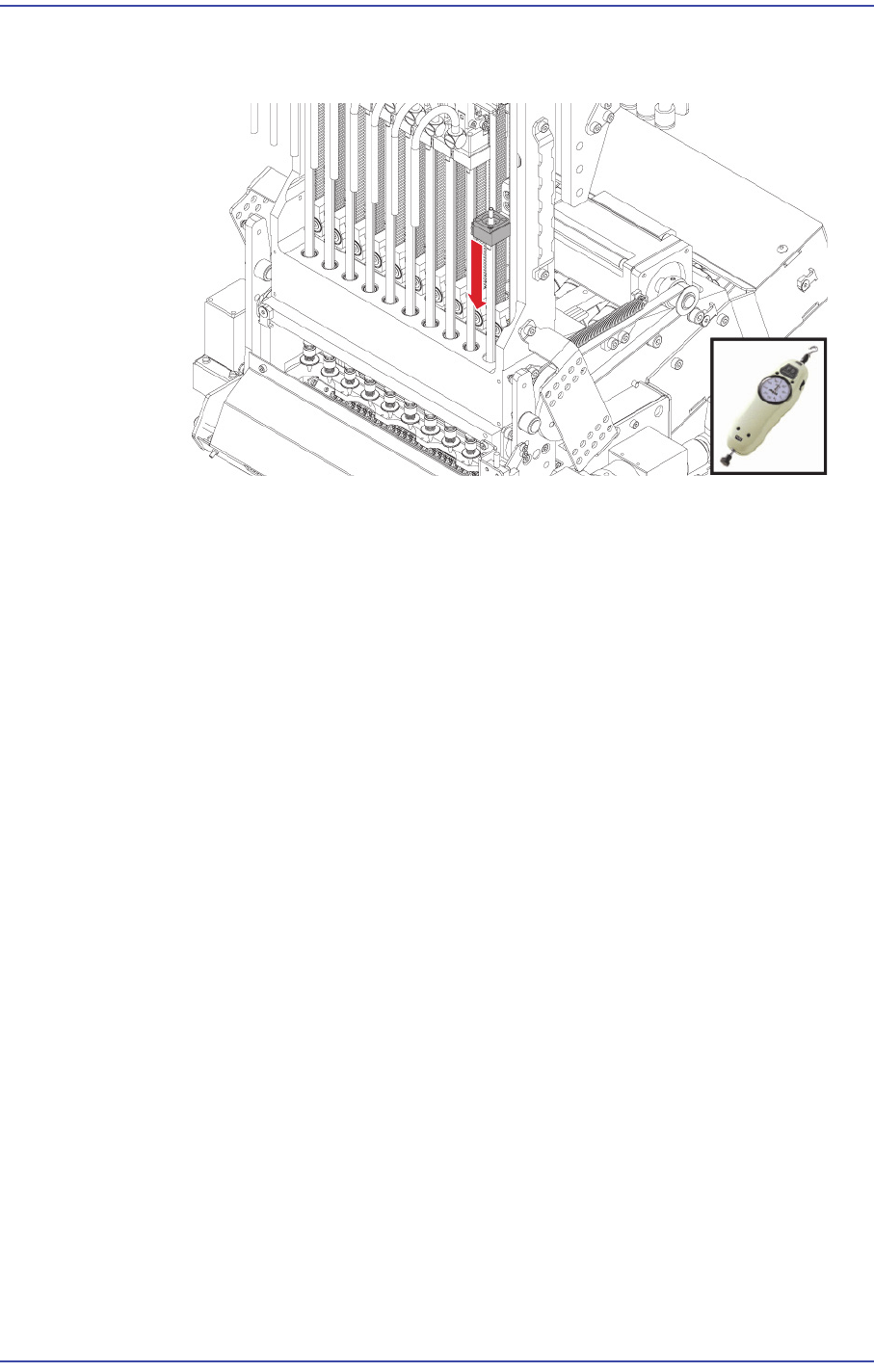
Measure the movement resistance in the downward direction and check whether it
is less than 0.050kgf using a push-pull gauge.
5-7
Head
Measure the movement resistance from the 2nd section to the 5th section below
the LM Guide tightening bolts.
14) Once the assembling is completed, turn on the main switch on the front of the machine
and boot the PC.
15) Perform the following calibrations.
Fiducial Cameras Offset Calibration
Camera Offset Calibration
Head Z & R Offset calibration
Total Time: 1Hour
5-8
Fast & Flexible Chip Shooter DECAN F2 Service Manual
5.3. Flying Module
5.3.1. Required Tools
T wrench (other tools supplied) or hex wrench
Gear wrench or torque wrench
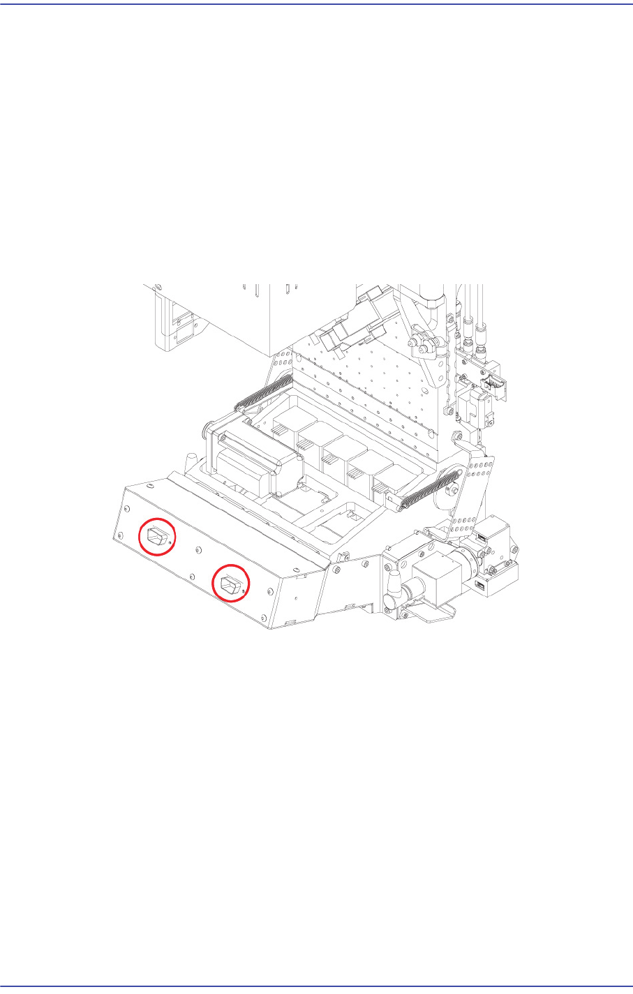
5.3.2. Flying IO Board Replacement Procedure
1) Manipulate the teaching box to move the head module to the front.
2) Close the PC as usual and turn off the main switch at the front of the machine.
3) Remove the connectors connected to board.
4) Unscrew the fixing bolts(8-M3*6) securing the flying IO board assembly using a hex
wrench and remove it