DECAN_F2_Service(Eng_Ver1).pdf - 第178页
6-28 Fast & Flexible Chip Shooter DECAN F2 Service Manual 8) Assemble the shuttle of the Exit Zone in the same manner .
6-27
Conveyor
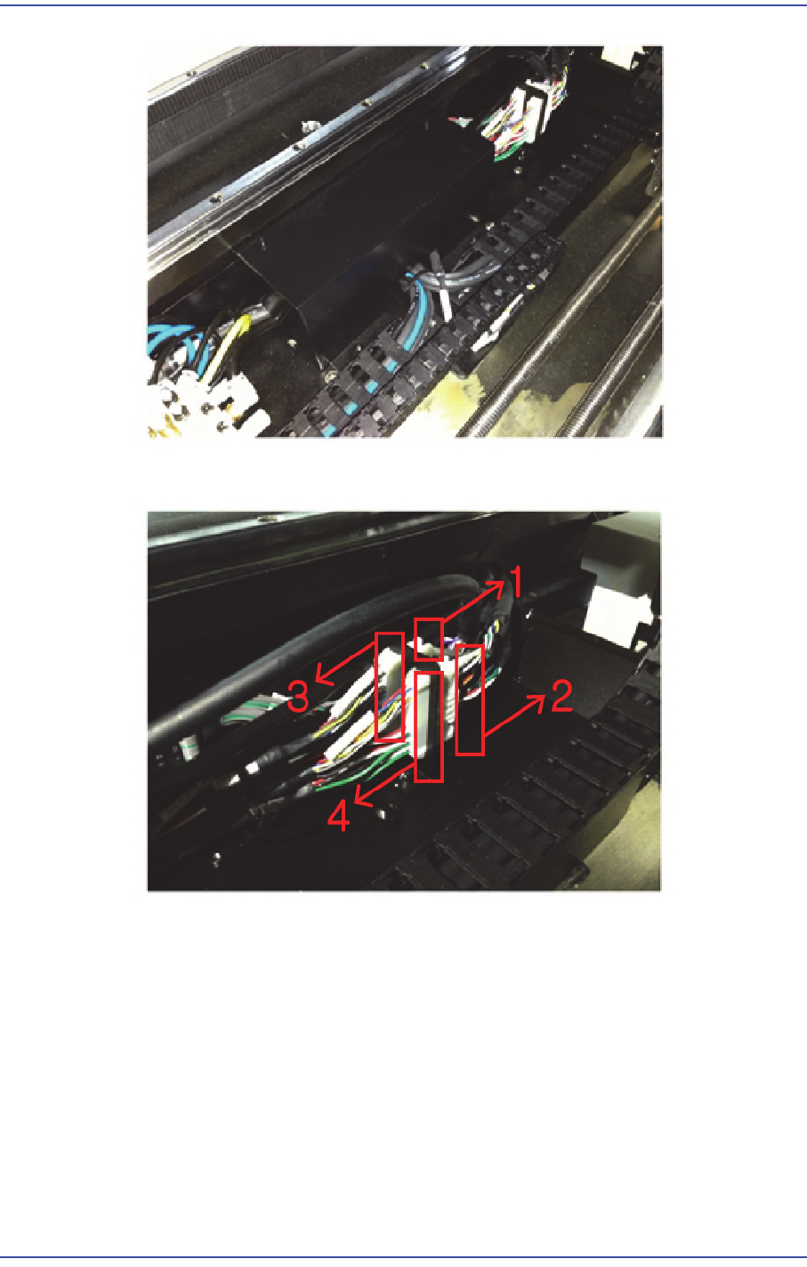
4) Remove connectors #1 ~ #4.
5) Remove the Entry Zone from the machine by performing steps #1~#4.
6) Assemble the Entry Zone for the Full Dual Conveyor in the reverse order of #1~#3.
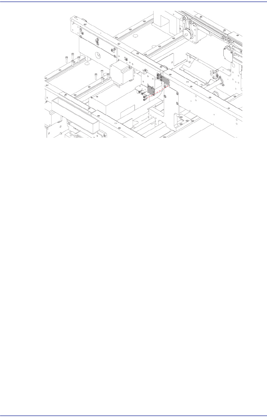
7) Remove the Connect Bracket of the Work Zone.
Match the Block Bracket of the Entry Zone to the connector groove of the Work Zone
and assemble the Connect Bracket.
6-28
Fast & Flexible Chip Shooter DECAN F2 Service Manual
8) Assemble the shuttle of the Exit Zone in the same manner.
6-29
Conveyor
6.6. Shuttle Conveyor Extension
6.6.1. Required Tools
T-Wrench (other tools supplied) or Hex Wrench
6.6.2. Extension Conveyor Replacement Procedure
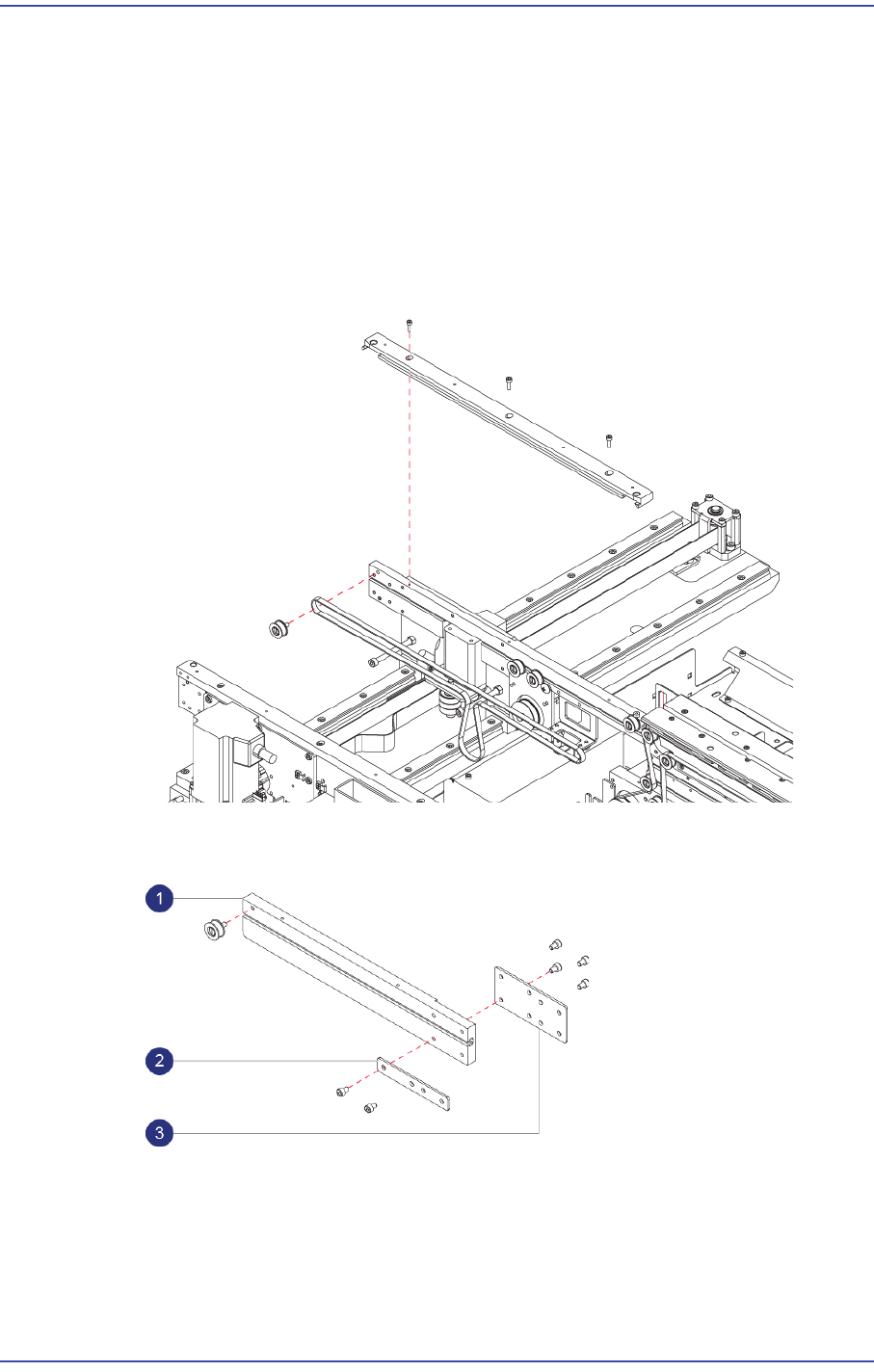
1) Remove the Guide Shuttle PCB at the Entry Zone, as well as the Idler Assembly at the
left most side, and the belt.
2) Assemble Fix 1 and 2 plates and the removed Idler Assembly to the connecting
Conveyor Frame.
1: Extension Frame / FC39-001379A
2: Extend Fix2 Plate / FC30-001735A
3: Extend Fix1 Plate / FC30-001734A
3) Assemble the connecting Conveyor Frame to the existing conveyor.