DECAN_F2_Service(Eng_Ver1).pdf - 第556页
18-36 Fast & Flexible Chip Shooter DECAN F2 Service Manual Gantry2 When performing calibratio n in S tation R2 by using the calibration tool. <Axis> combo box Select the axis to be compensated. Comp ensatio…
18-35
Machine Calibration
18.3.6. X-XY Compensation
This is performed to compensate the XY error that occurs while moving the X axis. If the
thermal mapping and gantry mapping have already been enabled, disable the mapping by
force to perform the X-XY compensation.
Caution X-XY compensation is performed at the factory before the
machine is shipped. An exclusive calibration tool is needed
to perform this calibration.
In general cases, skip this calibration process and perform
the next calibration process.
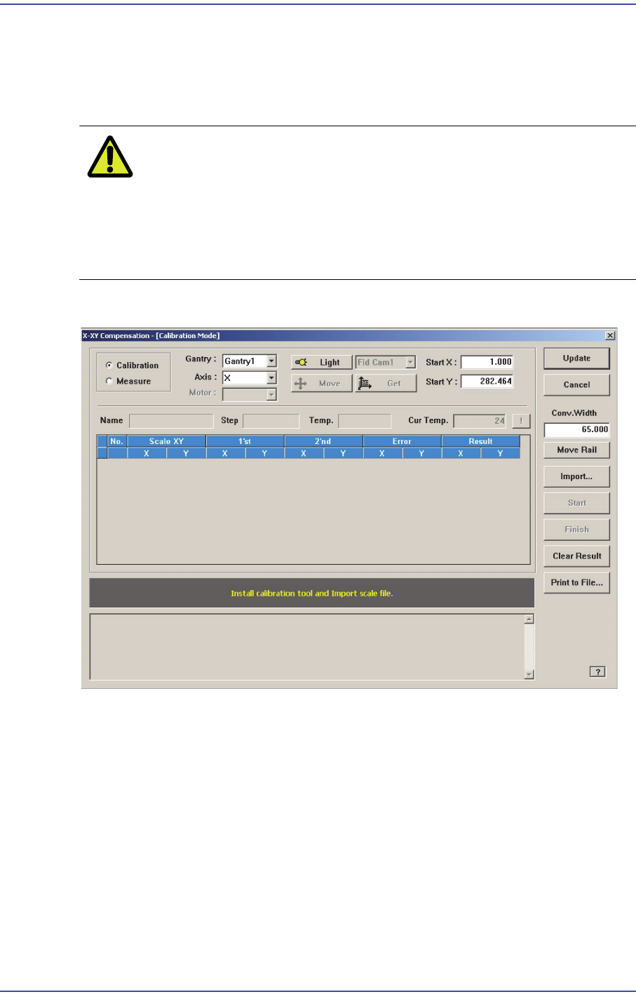
Figure18.12 "X-XY Compensation" dialog box
Mode Option button
Select the mode in which this process is to be performed.
<Calibration> Option button
Perform the X-XY compensation in the calibration mode and reflect the result.
<Measure> Option button
Perform the X-XY compensation in the measurement mode and do not reflect the
result. It is selected to measure the error for the Y axis.
<Gantry> combo box
Gantry1
When performing calibration in Station F2 by using the calibration tool.

18-36
Fast & Flexible Chip Shooter DECAN F2 Service Manual
Gantry2
When performing calibration in Station R2 by using the calibration tool.
<Axis> combo box
Select the axis to be compensated. Compensation can be made only for the X axis.
<Light> button
It is used to adjust the illumination so that the mark may be viewed clearly when
recognizing the fiducial mark of the calibration tool.
<Move /Get> button
It is used to teach fiducial mark #0 of the calibration tool.
<Start X /Start Y> edit box
Input the coordinate of fiducial mark #0 of the calibration tool. After selecting the edit
box, move the fiducial camera to the corresponding position by using the teaching box
and teach the corresponding mark correctly. Then click the <Get> button and input the
coordinate value here.
<Cur Temp> edit box
Input the current temperature at the time that the calibration is performed.
<Move Rail> button
Input the conveyor width in the <Conv. Width> edit box and click this button to adjust
the conveyor width.
<Import…> button
It is used to import the scale file for calibration.
<Start> button
It is used to start calibration after teaching fiducial mark #0 accurately.
<Finish> button
It is used to exit the work after the calibration is completed.
<Clear Result> button
Initializes the measurement result.
<Print to File…> button
It is used to output the result in text file format after completing calibration.
<Update> button
Apply the compensation value according to the calibration.
18-37
Machine Calibration
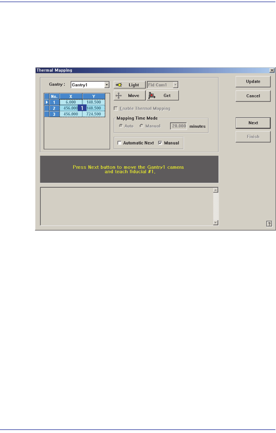
18.3.7. Gantry Thermal Mapping
The fiducial marks on the conveyer shall be taught at 3 points in order to compensate the
thermal deformation of the XY coordinate system due to the heat created by the friction of
the ball screw after operation of the machine.
Figure18.13 “Gantry Thermal Mapping” dialog box
1: Grid group
<Gantry> combo box
Select the gantry for which the thermal mapping is to be performed.
<Move> button
Move the fiducial camera of the corresponding gantry to the position of the fiducial
mark selected from the Grid group.
<Get> button
Apply the coordinate value of the current position as the selected fiducial mark
position.
<Enable Gantry Thermal Mapping> check box
Decides whether to carry out Gantry Thermal Mapping. When all the fiducials on the
transport rail are taught for Calibration, it will be checked automatically. To disable
the “Gantry Mapping”, remove the check from the check box.
<Mapping Time Mode> group
Set the cycle by which the mapping is performed.
Auto: Automatically performs the mapping by the cycle already determined.