DECAN_F2_Service(Eng_Ver1).pdf - 第521页
18-1 Machine Calibration Chapter18. Machine Calibration 18.1. Head [F2] Warning Changing the set up status by an unauthorized user could damage the machine or resu lt in personal injury. Unauthorized user must not change…
18-1
Machine Calibration
Chapter18. Machine Calibration
18.1. Head [F2]
Warning Changing the set up status by an unauthorized user could
damage the machine or result in personal injury.
Unauthorized user must not change the set up status of the
machine.
18.1.1. Head Tab dialog box
The <Head> command displays and sets the status of the head assembly Perform various
setups related to the head.
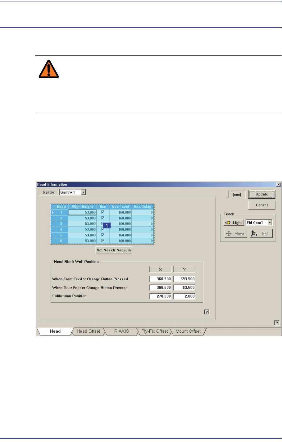
Figure18.1 “Sys. Setup : Gantry / Head Information” dialog box
1: Grid group
<Grid> group
Selects the gantry for which setup will be performed.
<Head No> column
Displays the head number.
<Align Height> column
Setup the Z-axis position when recognizing the parts.

18-2
Fast & Flexible Chip Shooter DECAN F2 Service Manual
The value “53.0” refers to the default value applied to this machine, which means
the position where the component is aligned on the top surface of the PCB.
<Use> column
Determines whether to use a head or not. If an error occurs concerning the head,
remove the selected head. However, in order to reassign the work assigned to the
corresponding head, execute the optimizer program again.
<Vac.Level> column
Indicates the pneumatic pressure level of the head with no nozzle set currently. If
necessary, the currently set value can be changed by inputting the pneumatic
pressure level of the head.
The base value is 160 and if the corresponding value exists between 100 and 220,
it is considered that the pneumatic system has no problem.
<Vac.Delay> column
Used to set the Vacuum Delay differently by heads. If a certain head cannot
perform work properly with a normal Delay due to a solenoid problem, input a
specific Delay value in the <Vac. Delay> column of the corresponding head. The
corresponding head then applies the Vacuum Delay with a higher priority than the
Vacuum Delay set during part registration to perform the work.
<Set Nozzle Vacuum> group
Measures the pneumatic pressure level of each head and indicates it in the
<Vac.Level> in the <Grid> group. Before clicking this button, the nozzles inserted
into the nozzle holder of each head must be removed first.
<Head Block Wait Position> group
Set the waiting position for the head assembly. To change the presently setup position,
newly teach the corresponding position.
<When Front feeder change button pressed> edit box
When the “Front feeder change” button on the front operation panel of the
machine is pressed, set the waiting position for the head assembly.
<When Rear feeder change button pressed> edit box
When the “Rear feeder change” button on the rear operation panel of the machine
is pressed, set the waiting position for the head assembly.
<Calibration Position> edit box
When performing calibration, set the position at which the head assembly waits.
<Gantry> Combo Box
Select the gantry for which setups related to head are to be performed.
<Teach> group
<Device> combo box