DECAN_F2_Service(Eng_Ver1).pdf - 第195页
8-5 BUT 7) Assemble in the BUT a new Sensor . Ref The part number of the new Senso r is J3212002A. 8) T urn on the main switch at the front of the machine and boot the PC once the replacement is completed. 9) Check the B…
8-4
Fast & Flexible Chip Shooter DECAN F2 Service Manual
8.2. Sensor
8.2.1. Required Tools
T Wrench (other tools supplied) or Hex Wrench
Torque Wrench
8.2.2. Sensor Replacement Procedure
1) Manipulate the teaching box to move the head assembly to both ends as much as
possible.
2) Turn on the main switch at the front of the machine and boot the PC once the
replacement is completed.
3) Manipulate the teaching box to increase the conveyor width.
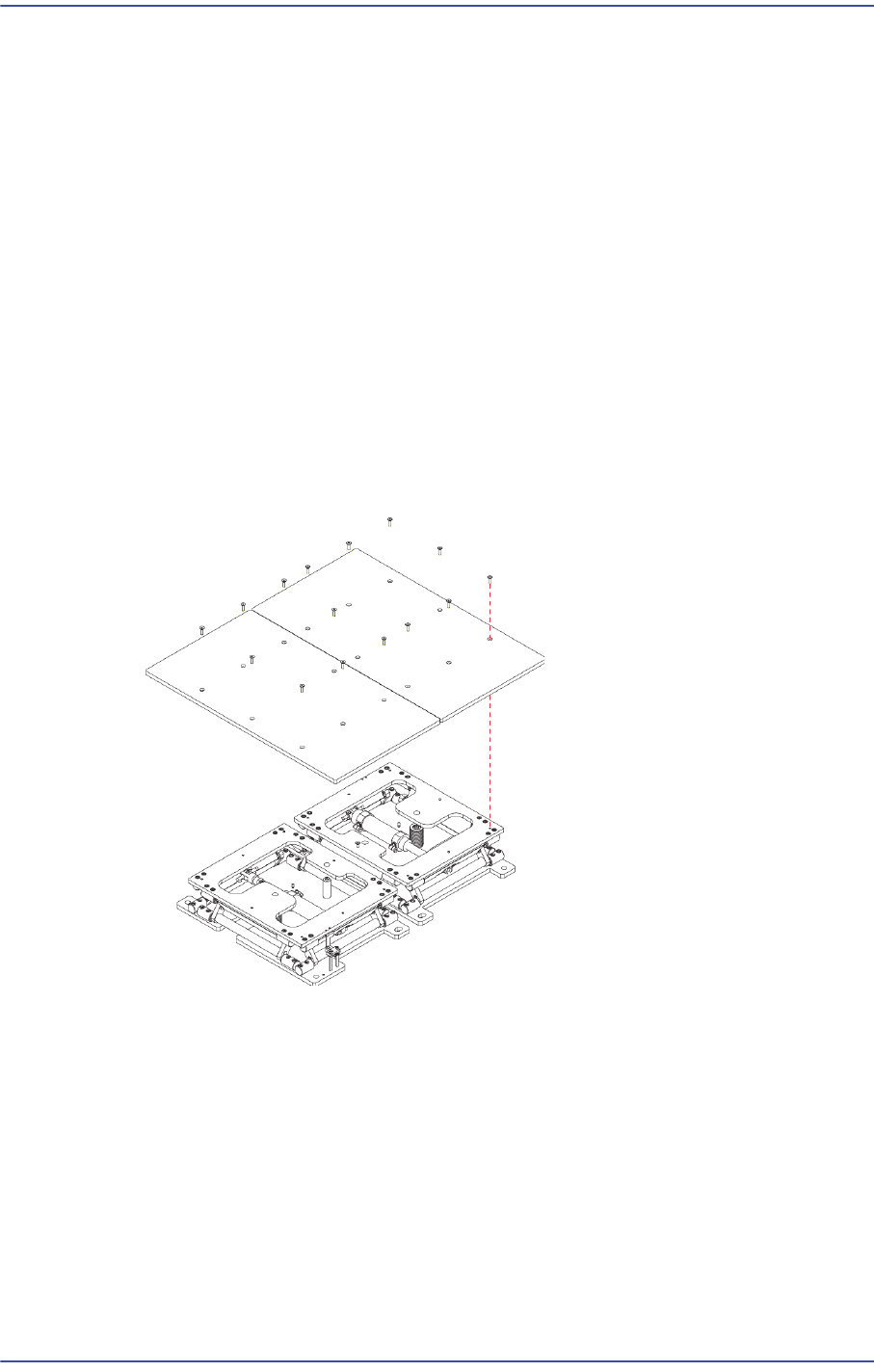
4) Unscrew the fixing bolts (8-M4*8) securing the Back Up Plate using a wrench and
remove it.
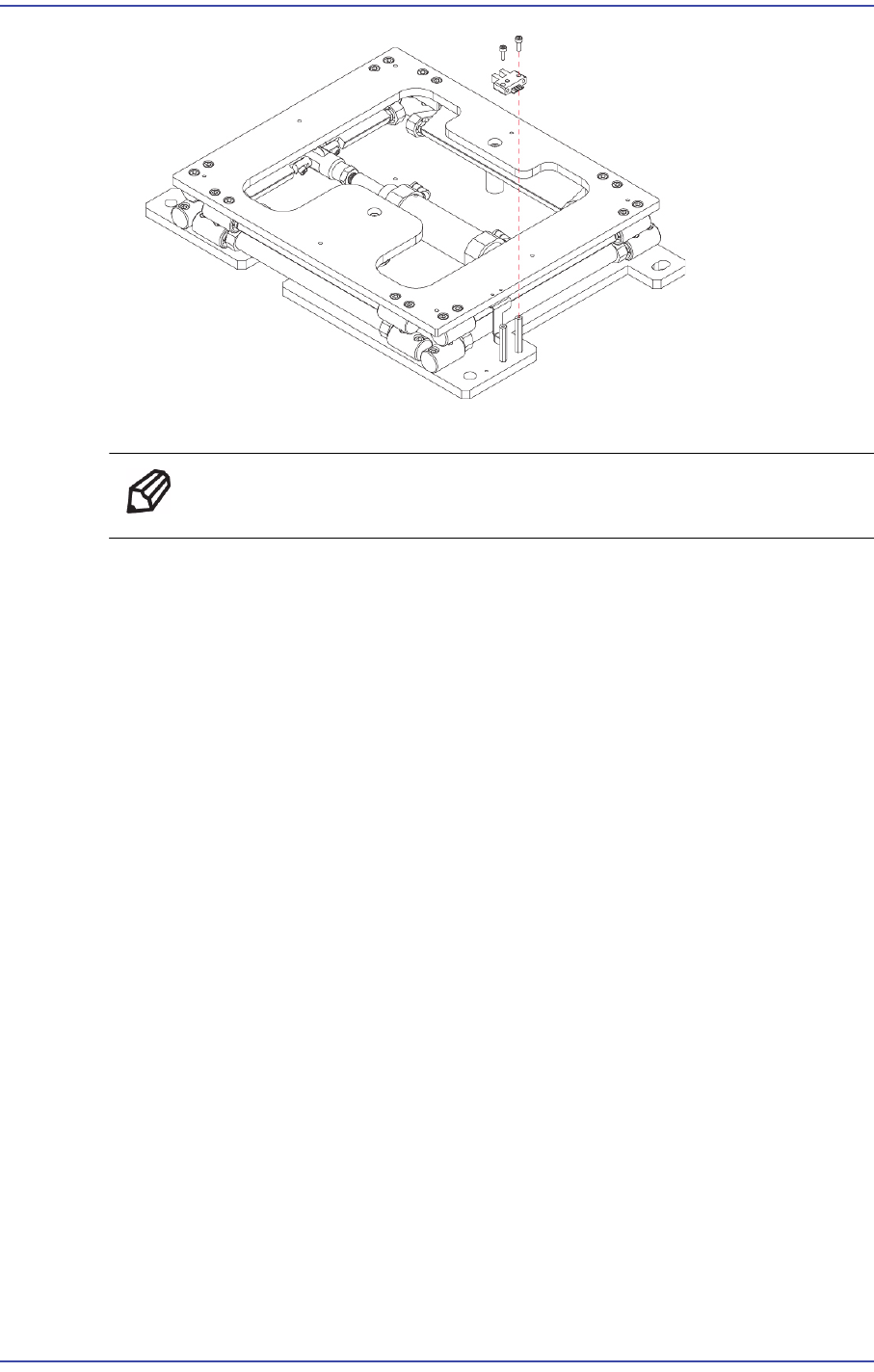
5) Disconnect the connector of the sensor to be removed.
6) Unscrew the fixing bolts (2-M3*10) securing the Sensor using a wrench and remove
it.
8-5
BUT
7) Assemble in the BUT a new Sensor.
Ref The part number of the new Sensor is J3212002A.
8) Turn on the main switch at the front of the machine and boot the PC once the
replacement is completed.
9) Check the BUT IO in> IO window - Diagnosis to run the MMI.

8-6
Fast & Flexible Chip Shooter DECAN F2 Service Manual
8.3. Spring
8.3.1. Required Tools
T Wrench (other tools supplied) or Hex Wrench
Torque Wrench
8.3.2. Spring Replacement Procedure
1) Manipulate the teaching box to move the head assembly to both ends as much as
possible.
2) Turn on the main switch at the front of the machine and boot the PC once the
replacement is completed.
3) Manipulate the teaching box to increase the conveyor width.
4) Unscrew the fixing bolts (8-M4*8) securing the Back Up Plate using a wrench and
remove it.
5) Unscrew the fixing bolts (16-M5*20) securing the Upper Table using a wrench and
remove it.