DECAN_F2_Service(Eng_Ver1).pdf - 第66页
3-4 Fast & Flexible Chip Shooter DECAN F2 Service Manual 3) Place the levelers simultaneously to adjust the level. Th e allowable tolerance must be adjusted within 0.05mm/m (1 scale is 0. 02mm). Perform measur ement …
3-3
Installation & Operation
Caution If the machine is installed on the floor made of shock-
absorbing material or wood that is not strong, excessive
vibration may occur during operation. Be sure to install the
machine on the strong and solid floor.
6) Install the machine that was move to the designated place after confirming the place of
the installation line from the responsible personnel of the customer.
7) Remove the vinyl sheet, internal packing material and desiccant.
Caution If the machine is unpacked by imposing excessive impact
on it, the machine cover may be damaged. Do not unpack
the machine by imposing excessive impact on it. .
3.1.3. Machine Installation
3.1.3.1. Required Tools
Leveler 4 sets (Specification: Leveler with accuracy higher than 0.02mm/m)
It is easy to use a leveler with an accuracy of 0.02 mm/m and 100 x 18 x 55 mm in
size.
Gear wrench for leveling (2 sets)
Vernier calipers
Crosshead (Phillips) screwdriver
Tester
Caution The approved and calibrated leveler must be used. Its
approval and calibration cycle is 1 year.
3.1.3.2. Installation Procedure of Stand-alone Machine
1) When installing the machine in the In-line system, adjust each foot to match the
conveyor reference surface with the previous and following machines. Align the
reference surface between machines within 0.05mm from the left and right. Remove
the front and rear covers before adjusting the height
2) Set the reference level of the machine to 900mm and 950mm based on the conveyor
surface (European standard, CE). However, a deviation of 0 ~ ±15 mm is allowed
depending on the condition (inclination) of the floor’s surface.
3-4
Fast & Flexible Chip Shooter DECAN F2 Service Manual
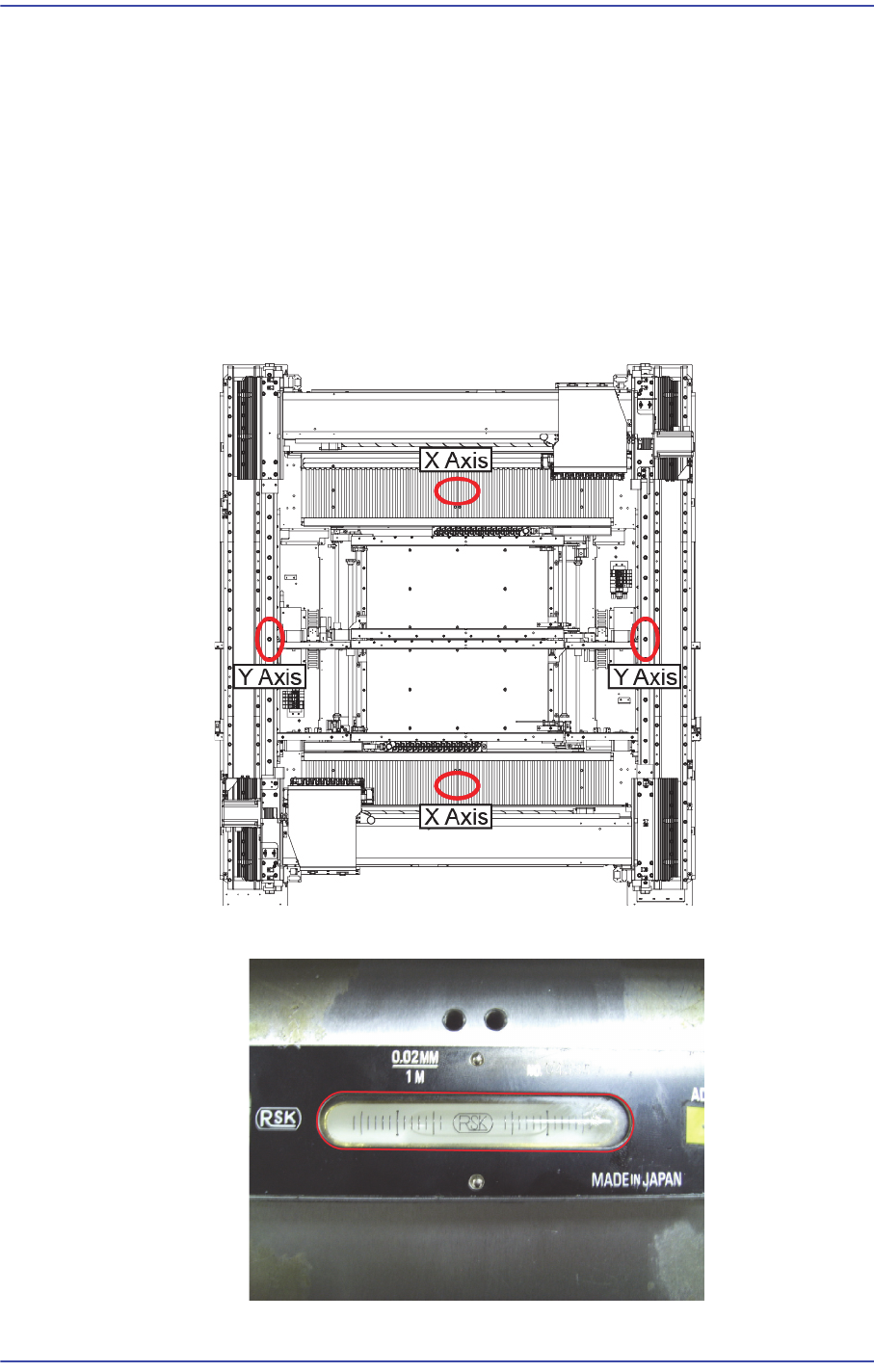
3) Place the levelers simultaneously to adjust the level. The allowable tolerance must be
adjusted within 0.05mm/m (1 scale is 0.02mm). Perform measurement by using 2 sets
of the levelers simultaneously.
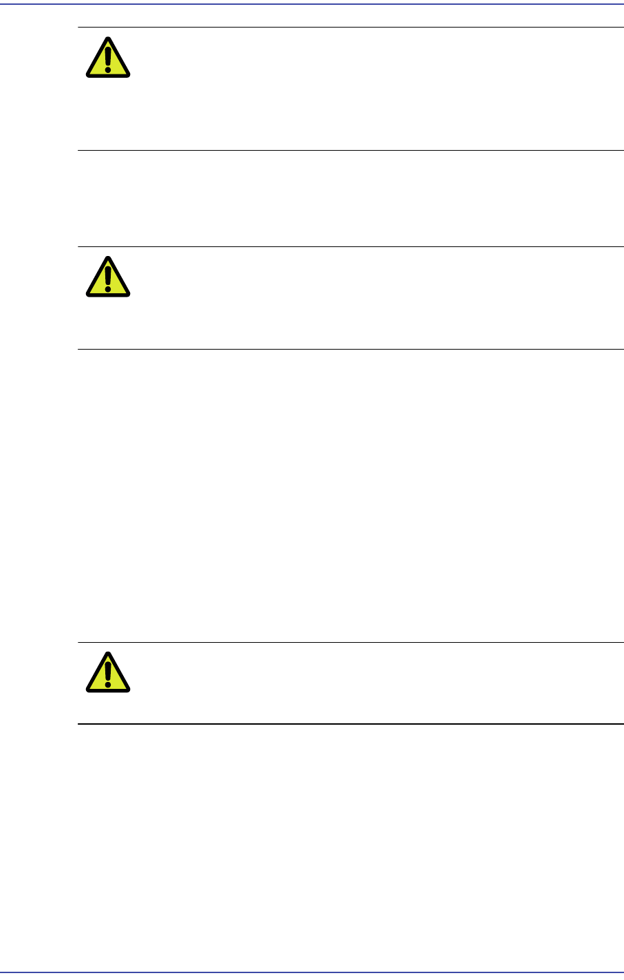
Measuring position
XY-axis Direction
Push the X Gantry to the rear as far as possible and place the head in the
middle. Push the head to the rear side as far as possible, place two level
gauges on the middle of the upper surface of the Y-axis LM Guide and then
conduct measurement. (The center of the level is located on the 13th hole from
the LM Guide hole as a reference.)
1: X Axis Leveler
3-5
Installation & Operation
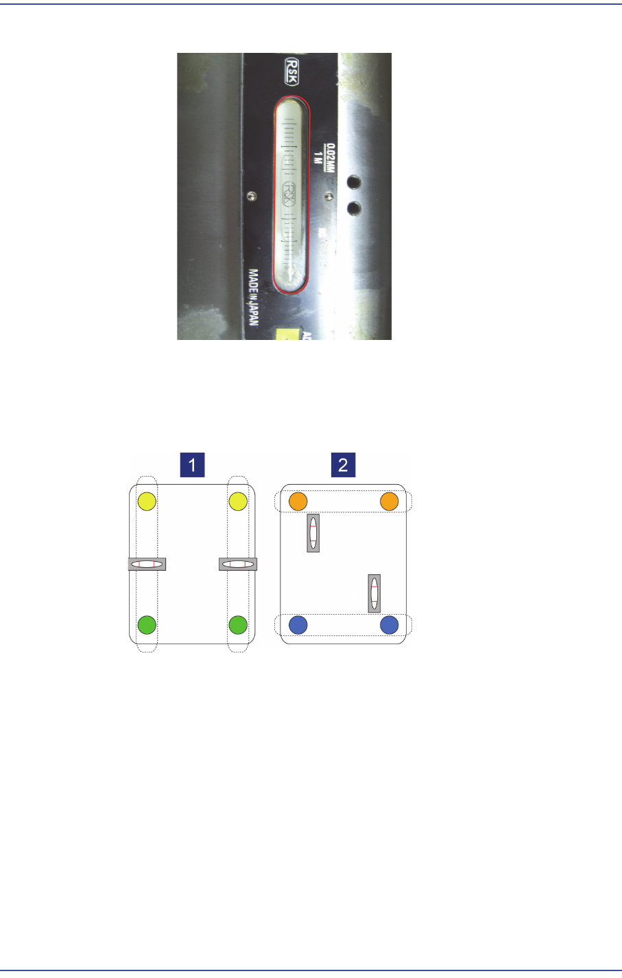
2: Y Axis Leveler
4) When adjusting the level of the foot, it is recommended to group 2 feet as one set and
adjust the level in each direction. (At this time, adjust the foot finally.)
Leveling in the front-rear direction: Adjust feet at the front and rear in pair
Leveling in the left-right direction: Adjust feet at the left and right in pair
5) The feet of the machine must be supported at uniform force, which is adjusted by
tightening the lock nut of the foot so that uniform force is applied to the feet. Check if
there is any loose foot. Tighten the lock nuts for 4 legs after leveling is finished.