DECAN_F2_Service(Eng_Ver1).pdf - 第592页
18-72 Fast & Flexible Chip Shooter DECAN F2 Service Manual 1 1. .Select Gantry 2 in the <Gantry> comb o box and perform calibration in the same manner as has been d one for Gantry 1. The result value can be con…
18-71
Machine Calibration
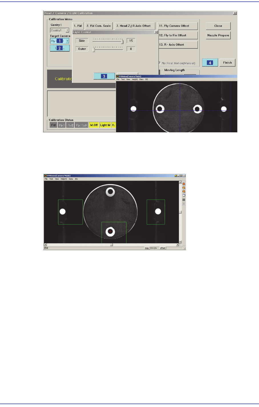
7. In order to perform calibration, first recognize the reference fiducial mark of the head
and measure the R Offset of the fly camera. Then recognize the 2 fiducial marks on the
bottom surface of the calibration tool using the fiducial camera and measure the scale
of the fly camera.
8. If it is completed, Click the <Next> button.
9. Then the message “Next, Remove the Calibration Tool From Head 1. Click [Next] for
Moving Down Head. After Moving, Remove the Tool Manually” appears. Click the
<Next> button to remove the calibration nozzle from the nozzle-holder of Head #1
manually.
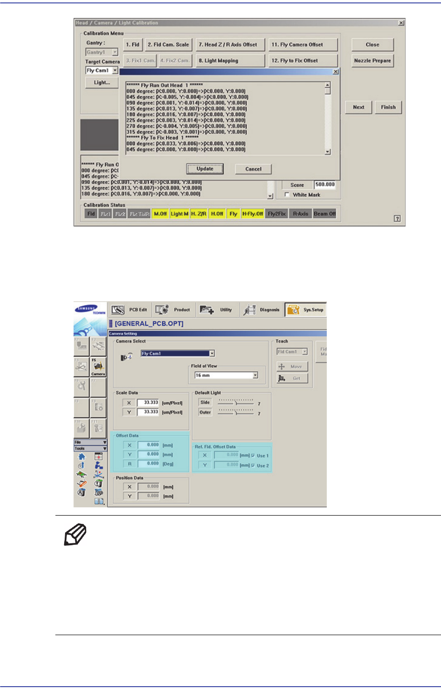
10. .From Head #2 to Head #6, perform calibration in the same manner as it was
performed for Head #1.If the calibration procedure is completed for all heads
normally, the result is displayed as shown in the following figure.
18-72
Fast & Flexible Chip Shooter DECAN F2 Service Manual
11. .Select Gantry 2 in the <Gantry> combo box and perform calibration in the same
manner as has been done for Gantry 1.
The result value can be confirmed in the Camera dialog box in the System Setup
menu.
Memo The reference values for the calibration of the Head-Fly Offset is as
follows. (FOV 25 MEGA) [Unit : X(mm) , Y (mm) , R (°) ]
Offset X : -0.60 ~ 0.60 (mm)
Offset Y : -0.60 ~ 0.60 (mm)
Offset R : -1.0° ~ 1.0°
18-73
Machine Calibration
18.3.10.7. Fly to Fix Camera & Fly Runout Offset Calibration
Calibrates the relation between the Fly camera and Fix camera. The calibration is
performed to compensate the offset that occurs due to the difference between the ‘part-
alignment height’ and placement height when placing the part after part-recognition by the
fly-camera.
The offset that occurs this time is caused by the run-out, bending of an axis, etc. Perform
compensation of the value at the recognition height of the fly camera and fiducial camera,
which are the same as the placement height.
In order to perform calibration of this, first check if the calibration tool is placed on the
calibration tool position of the front ANC.
The following is the procedure to calibrate the ‘Fly to Fix Offset’
1. Click the <Nozzle Prepare> button and insert the CN400 nozzle into the No. 1 hole of
the ANC manually.
2. If the <12. Fly to Fix Offset> is clicked after selecting the <Automatic Next> check
box, calibration is performed for the selected gantry automatically.
If calibration is performed after selecting the <No Real Motion [Manual]> check box,
the nozzle is inserted into each head manually. Click the <Next> button to move onto
the next step.
If calibration is performed without selecting either the <Automatic> check box or
<Manual> check box, the nozzle is changed automatically for the currently selected
nozzle. Click the <Next> button to move onto the next step.
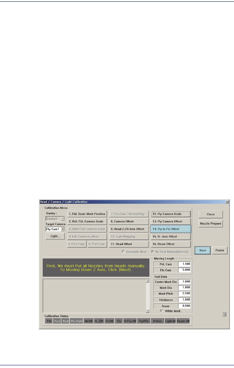
3.
If the <12. Fly to Fix Offset> button is selected, the message “First, We must Put all
Nozzles From Heads on Manually. To Move down Z Axis, Click [Next]” appears.