DECAN_F2_Service(Eng_Ver1).pdf - 第193页
8-3 BUT Check if the cylind er is stuck during movement while pressing the upper plate by hand. If it is not stuck, tighten the set scre w that was previously tightened slightly . When assembling the ring fixe r , tigh…
8-2
Fast & Flexible Chip Shooter DECAN F2 Service Manual
and replace the module. At this time, do not remove the upper plate.
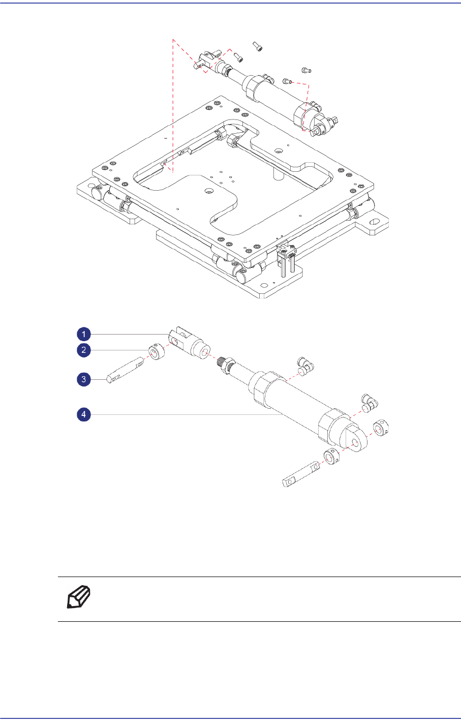
6) Remove it as shown in the following figure, the Cylinder.
1: Cylinder Joint : J6619062A
2: Ring Fixer : J7053795A
3: Cylinder Joint Pin : J70530794B
4: Cylinder : J67010088B
Ref The part number of the new Cylinder is J67010088B.
7) After assembling with a new Cylinder, refer to the following.
Secure 2 sets of the ring fixer on the cylinder body side with set screws first and then
slightly tighten the ring fixer on the cylinder joint with set screws (M4 - 2 sets).

8-3
BUT
Check if the cylinder is stuck during movement while pressing the upper plate by
hand. If it is not stuck, tighten the set screw that was previously tightened slightly.
When assembling the ring fixer, tighten the set screws of the ring fixer to have it
contact with the cylinder joint without pressing the screw hard by hand.
Apply grease sufficiently between the cylinder joint pin and ring fixer, and press the
upper plate by hand repeatedly so that the grease smears well.
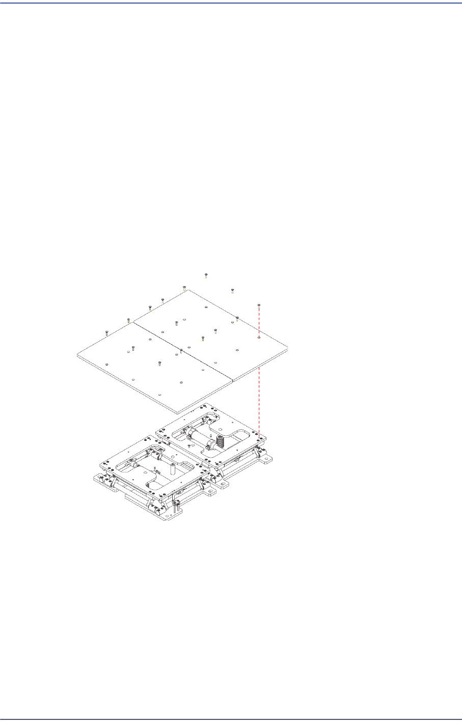
Connect the air tube to the cylinder fitting and assemble the back-up plate by using
fixing screws.
8) Assembled the reverse order of disassembling.
Turn on the main switch at the front of the machine and boot the PC once the
replacement is completed.
9) Check the> Cylinder Check BUT Speed - > IO - Diagnosis is allowed to run the
MMI
8-4
Fast & Flexible Chip Shooter DECAN F2 Service Manual
8.2. Sensor
8.2.1. Required Tools
T Wrench (other tools supplied) or Hex Wrench
Torque Wrench
8.2.2. Sensor Replacement Procedure
1) Manipulate the teaching box to move the head assembly to both ends as much as
possible.
2) Turn on the main switch at the front of the machine and boot the PC once the
replacement is completed.
3) Manipulate the teaching box to increase the conveyor width.
4) Unscrew the fixing bolts (8-M4*8) securing the Back Up Plate using a wrench and
remove it.
5) Disconnect the connector of the sensor to be removed.
6) Unscrew the fixing bolts (2-M3*10) securing the Sensor using a wrench and remove
it.