DECAN_F2_Service(Eng_Ver1).pdf - 第551页
18-31 Machine Calibration 18.3.5.1. Procedure Conveyor Calibration method is as follows. 1. “Click the <Home All> button in th e “Conv eyor Calibration” dialog box. 2. Select the station to be calib rated from the …
18-30
Fast & Flexible Chip Shooter DECAN F2 Service Manual
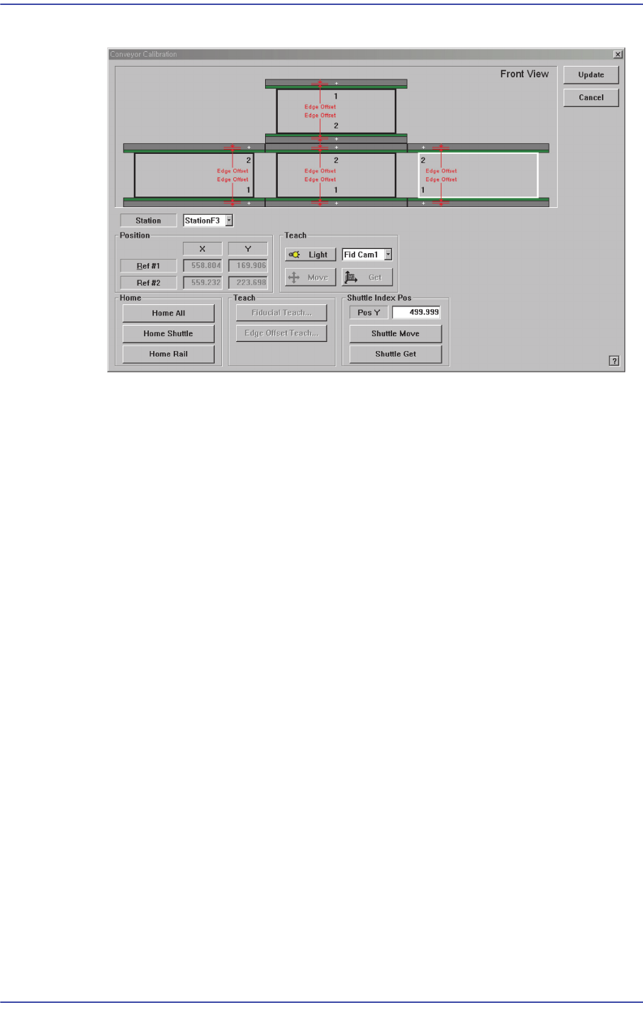
Figure18.11"Conveyor Calibration-Shuttle Index Pos " dialog box
<Pos Y> edit box
Refers to the coordinate of the outlet position (index position) of the current exit
shuttle.
<Shuttle Move> button
Moves the shuttle to the position inputted in the <Pos Y> edit box. However, if the
rear rail is fixed, it moves the shuttle to the position less the width of the current
rail.
<Shuttle Get> button
Sets the current shuttle position as the coordinate of the machine. Move the exit
shuttle using the jog function of the teaching box to match it with the fixed rail of
the next machine, and click this button to input the coordinate of the shuttle index
position in the <Pos Y> edit box.
In the case of the equipment with fixed rear rail, adjust the conveyor width so that
it becomes identical to the conveyor width of the following equipment, and move
the exit shuttle to the position that allows PCB transfer between two equipments
using the jog function and then click this button to save the coordinate of the
shuttle index position. At this time, input the value obtained by adding the width
of the current rail to the current position in the <Pos Y> edit box.
[Setup Sequence of the Jog Function of the Teaching Box]
Jog Conveyor Station Shuttle Axis
18-31
Machine Calibration
18.3.5.1. Procedure
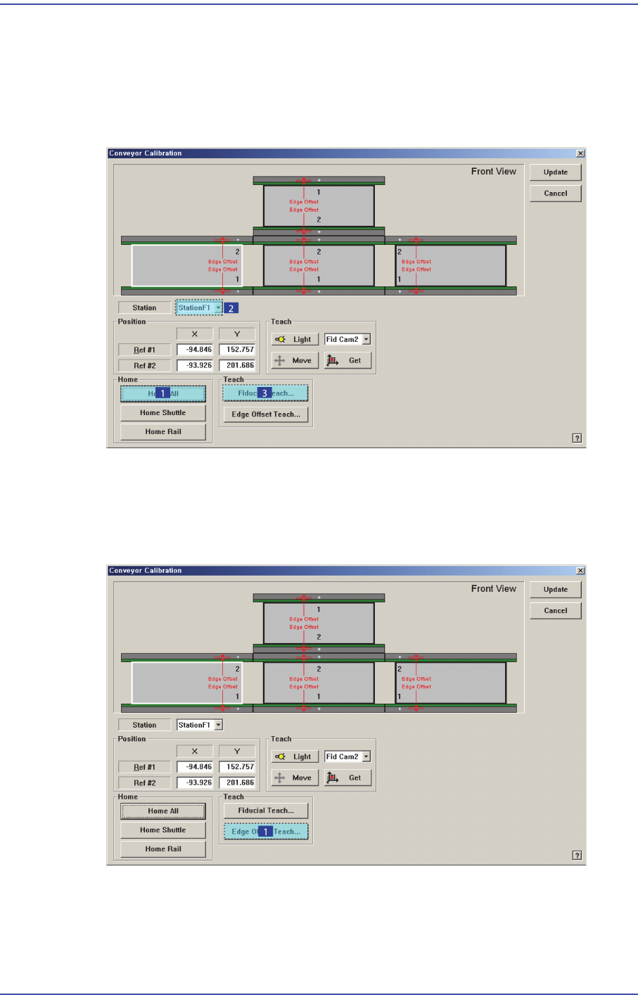
Conveyor Calibration method is as follows.
1. “Click the <Home All> button in the “Conveyor Calibration” dialog box.
2. Select the station to be calibrated from the <Stations> combo box.
3. Click the <Fiducial Teach…> button to teach the fiducial marks of the selected station
accurately and click the <Tuning> button to scan the position accurately.
4. Click the <OK> button to update the information on the fiducial mark position.
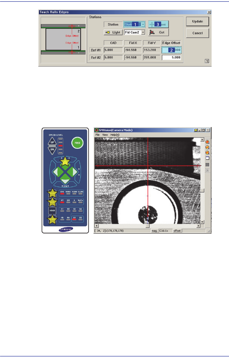
5. Click the <Edge Offset Teach…> button
6. .Select the station to be calibrated from the <Stations> combo box.
7. Select the <Edge Offset> edit box corresponding to the “Ref. #1” and click the <Move
Cam> button.
18-32
Fast & Flexible Chip Shooter DECAN F2 Service Manual
8. Then the downward camera (fiducial camera) moves to the corresponding position of
the fiducial mark. Select XY by pressing the ‘AXIS’ button using the teach box to
make the backup table rise and make the edge of the transport rail frame correspond
with the horizontal line of the cross lines in the vision.
Then select the jog by pressing the ‘MODE’ button, and slowly move by pressing the
Y(+) direction move button.
9. When matched, press the ‘Enter’ button in the teaching box.
10. Select the corresponding <Edge Offset> edit box in ‘Ref. #2’ and click the <Move
Cam> button.
11. Perform teaching on ‘Ref. #2’ in the same way as teaching on ‘Ref. #1’.