DECAN_F2_Service(Eng_Ver1).pdf - 第540页
18-20 Fast & Flexible Chip Shooter DECAN F2 Service Manual 18.3.3. Fiducial Camera Scale In the case of the DECAN G2 model, since it has no fix camera , in most cases the calibration must be performed by using th e f…
18-19
Machine Calibration
First, move the X frame manually to the center of equipment.
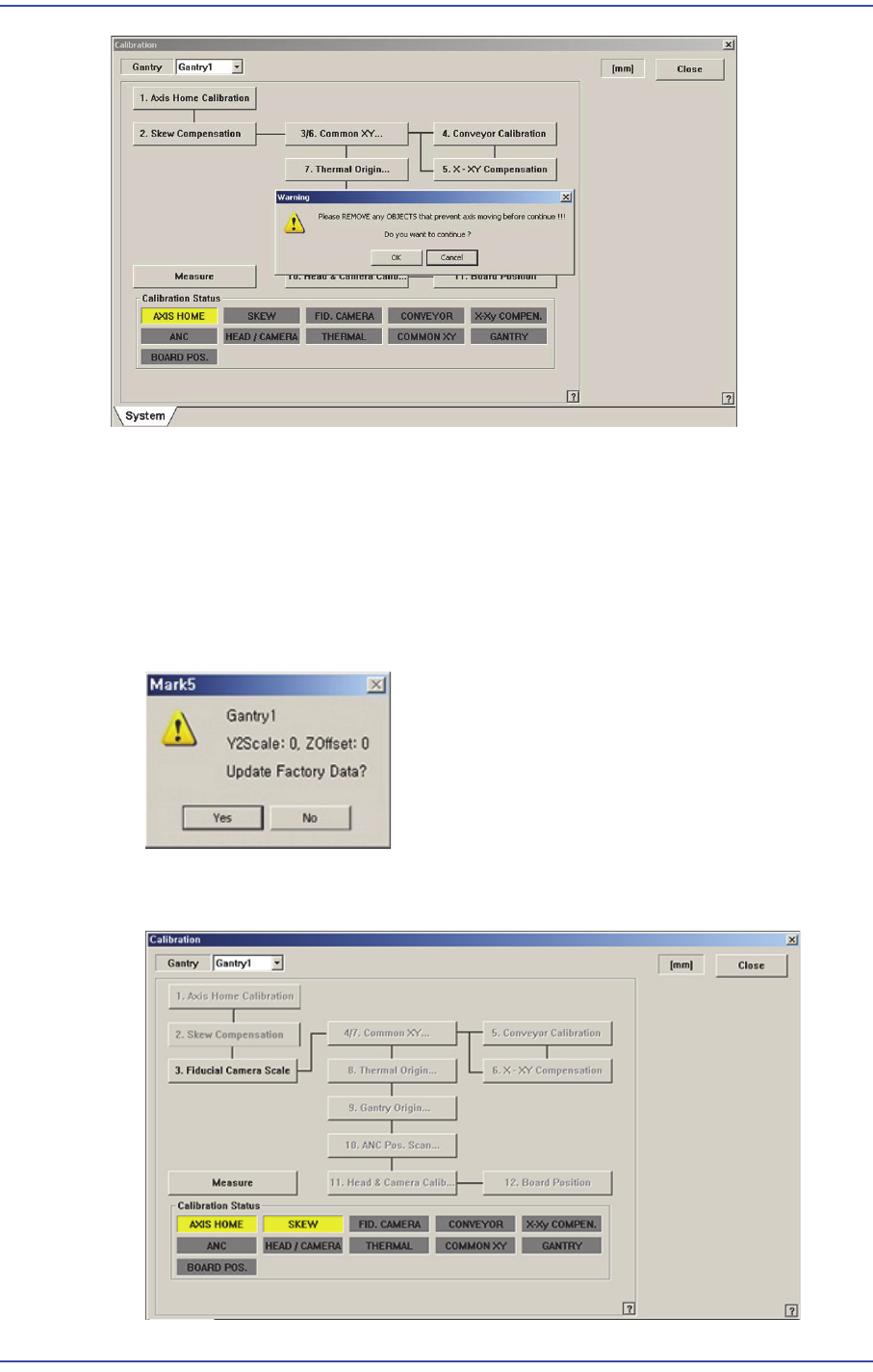
Click on the <Skew compensation> button. Automatic homing on Z-axis is performed,
Y1-axis motor rotates and moves X frame until detecting the Y home sensor. Once the
home sensor has been detected, move to the Y-axis movement distance (Y Stroke) in
the opposite direction, and move to the opposite direction again until the Y Home
sensor is detected.
Then, ‘Skew’ information is shown as follows, and asks whether to apply the value.
Click on the <Yes (Y)> button and <Update> button, and then homing of the
equipment is newly done in accordance with the applied skew information.
18-20
Fast & Flexible Chip Shooter DECAN F2 Service Manual
18.3.3. Fiducial Camera Scale
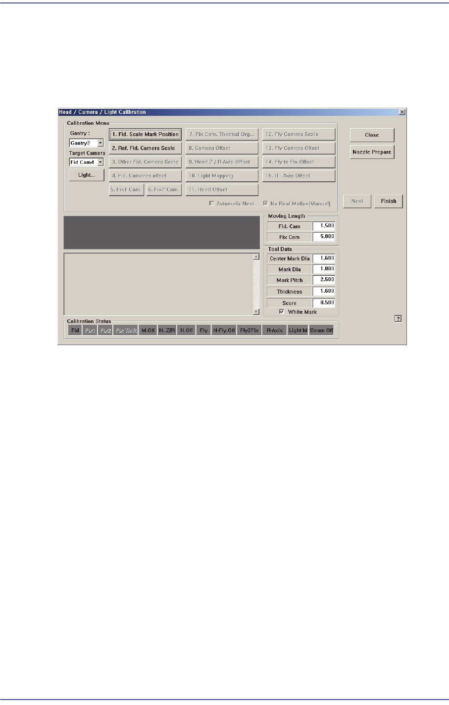
In the case of the DECAN G2 model, since it has no fix camera, in most cases the
calibration must be performed by using the fiducial camera. Therefore, the scale
calibration of the fiducial camera must be performed first.
If the fiducial camera is not calibrated, the rest of the buttons are disabled.
<1. Fid. Scale Mark Position> button
Set the position of the reference fiducial mark located at the top surface of the ANC.
When performing the scale calibration of the fiducial camera by using the calibration
tool, place the calibration tool at the position for the calibration tool on the front ANC.
18-21
Machine Calibration
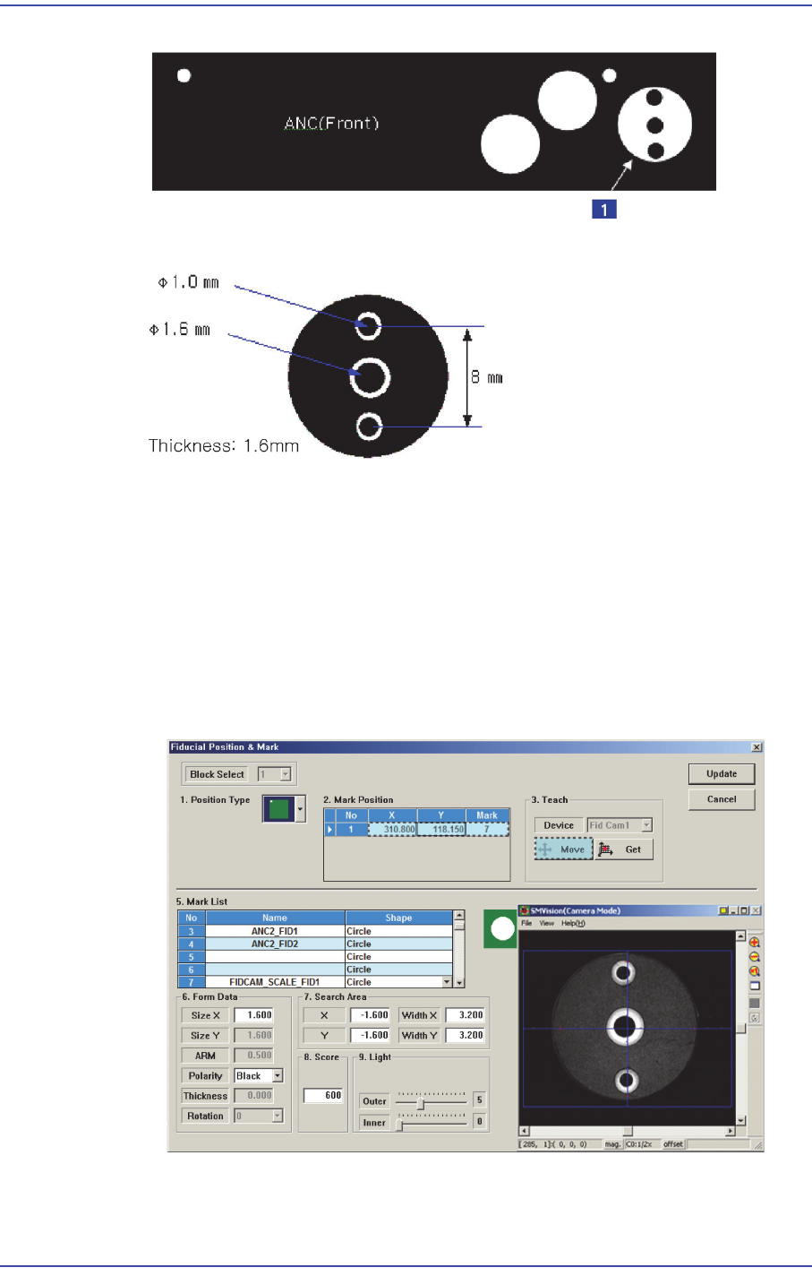
1:Calibration Tool position
The following is the process that performs teaching of the calibration tool placed on
the top surface of the ANC by using the fiducial camera.
1. When performing the mark setup, select the gantry and click the <1. Fid. Scale
Mark Position> button. If the following screen appears, click the <Move> button
in the <Teach> group.
Then the fiducial camera moves to the corresponding position. The mark ID of
Gantry 1 is fixed as No. "7", and No. "8" for Gantry 2.
2. If the corresponding fiducial mark cannot be recognized correctly, teach the
position of the fiducial mark at the center of the calibration tool placed on the top