DECAN_F2_Service(Eng_Ver1).pdf - 第143页
5-43 Head 5) Unscrew the fixing bolts(2 -M2*6) securing sensor and remove it. 6) Once the assembling is completed, turn on th e main switch on the front of the machine and boot the PC.
5-42
Fast & Flexible Chip Shooter DECAN F2 Service Manual
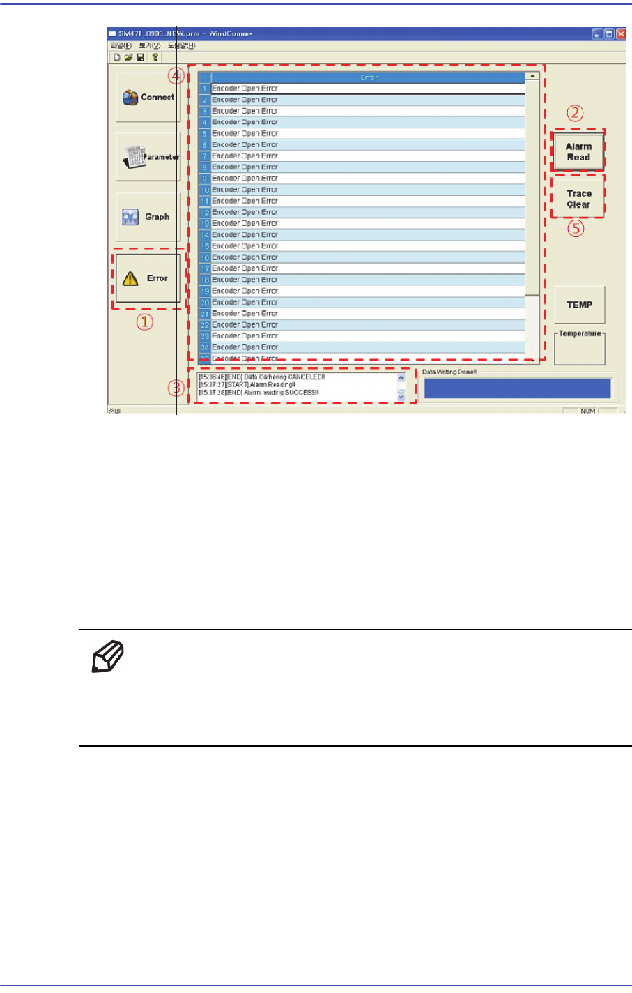
1: Run the Windcom+ Program and click the ‘Error’ button.
2: Click the ‘Alarm Read’ button to read the alarm of the currently connected Head
AMP.
3: When the alarm is read correctly, the ‘Alarm Read Success’ message is outputted in
the status window and the error message can be checked in the Error display window.
4: After checking the error, capture and save the screen according to the file saving
rule as specified in the manual.
5: Click ‘Trace Clear’ to delete the alarm history saved in the Head AMP.
Ref 'When the Alarm Read / Clear Failed message is outputted in the
status window using the ‘Alarm Read' and 'Trace Clear' buttons, set
the Windcomm+ and Head AMP communication.
5.9.4. Sensor Replacement Procedure
1) Manipulate the teaching box to move the head module to the front.
2) Close the PC as usual and turn off the main switch at the front of the machine.
3) Remove the spindle at the location where the spindle is replaced referring to the
Spindle Replacement Procedure.
4) Remove the connector connected to sensor.
5-43
Head
5) Unscrew the fixing bolts(2-M2*6) securing sensor and remove it.
6) Once the assembling is completed, turn on the main switch on the front of the machine
and boot the PC.
5-44
Fast & Flexible Chip Shooter DECAN F2 Service Manual
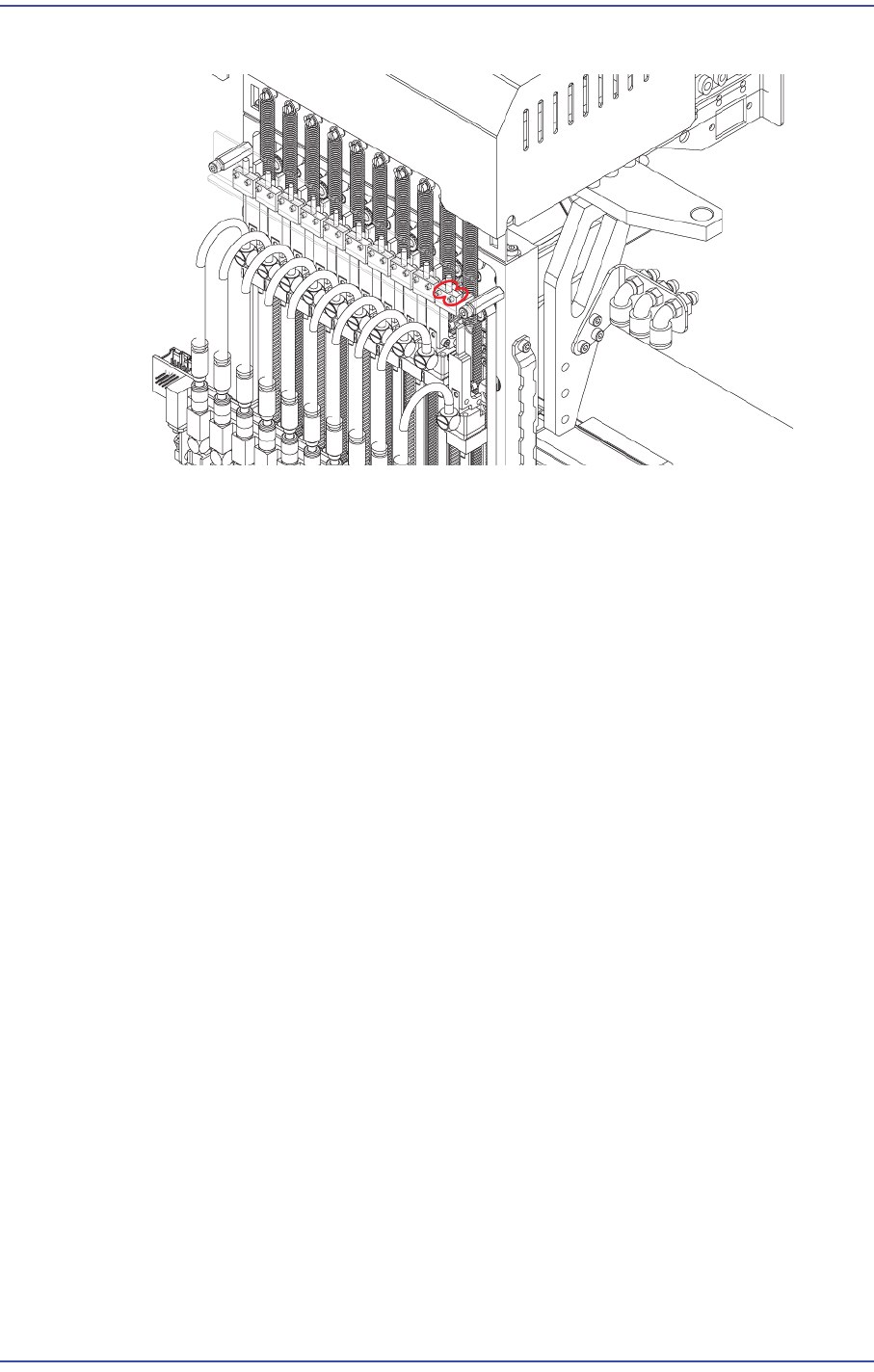
5.9.5. How to replace the Z-axis sensor individually (Z1~Z5)
1) Remove the R-axis home sensor cable from the machine as shown in Figure 1.
After removing the CN12 connector of the Head IF board, remove the R-axis home
sensors (5 sets).
2) Remove the area treated with a shrink tube as shown in Figure 1.
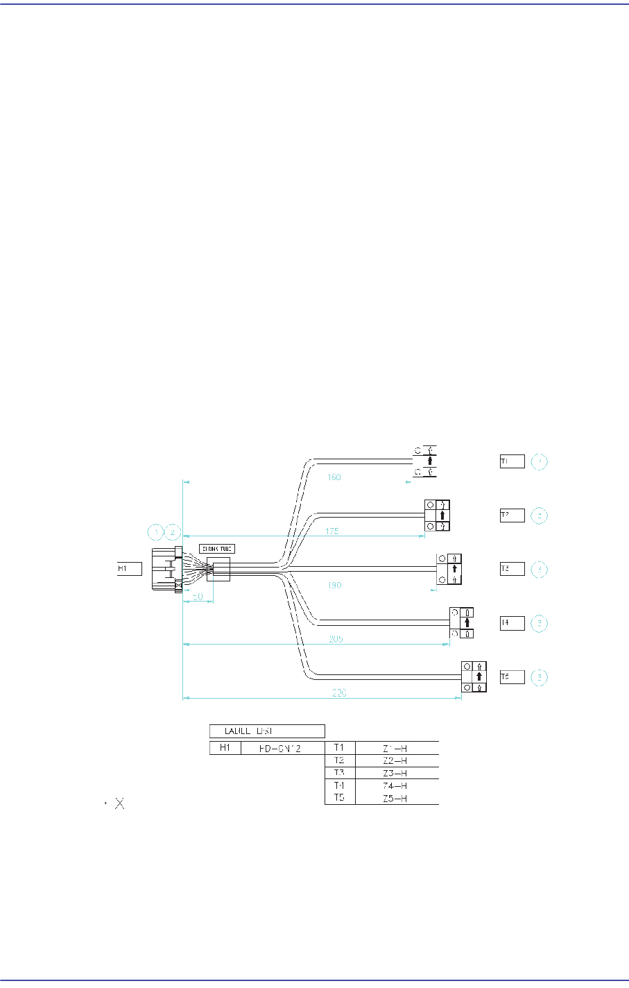
3) Replace the R-axis home sensor.
R1 Home Sensor: Connect the sensor to A1/A4/B4 referring to Figure 2.
R2 Home Sensor: Connect the sensor to A2/A5/B5 correctly referring to Figure 2.
R3 Home Sensor: Connect the sensor to A3/A6/B6 correctly referring to Figure 2.
R4 Home Sensor: Connect the sensor to A2/B1/B5 correctly referring to Figure 2.
R5 Home Sensor: Connect the sensor to A3/B2/B6 correctly referring to Figure 2.
4) After replacing the Z-axis sensor, finish the area where the connector and cable is
connected and then they are treated with a shrink tube by using insulation tape so that
current does not leak out.
5) After replacing the sensor, connect the connector to the Head I/F board and connect
the Z-axis home sensors (5 sets) to the head spindle again.
Z Axis Home Sensor Cable