DECAN_F2_Service(Eng_Ver1).pdf - 第388页
15-14 Fast & Flexible Chip Shooter DECAN F2 Service Manual 15.6. Rear Power Panel 15.6.1. Required Tools Crosshead (Phillips) screwdrive r and flathead screwdriver T W rench or Hex W rench 15.6.2. Part list of Re…
15-13
Electric Device
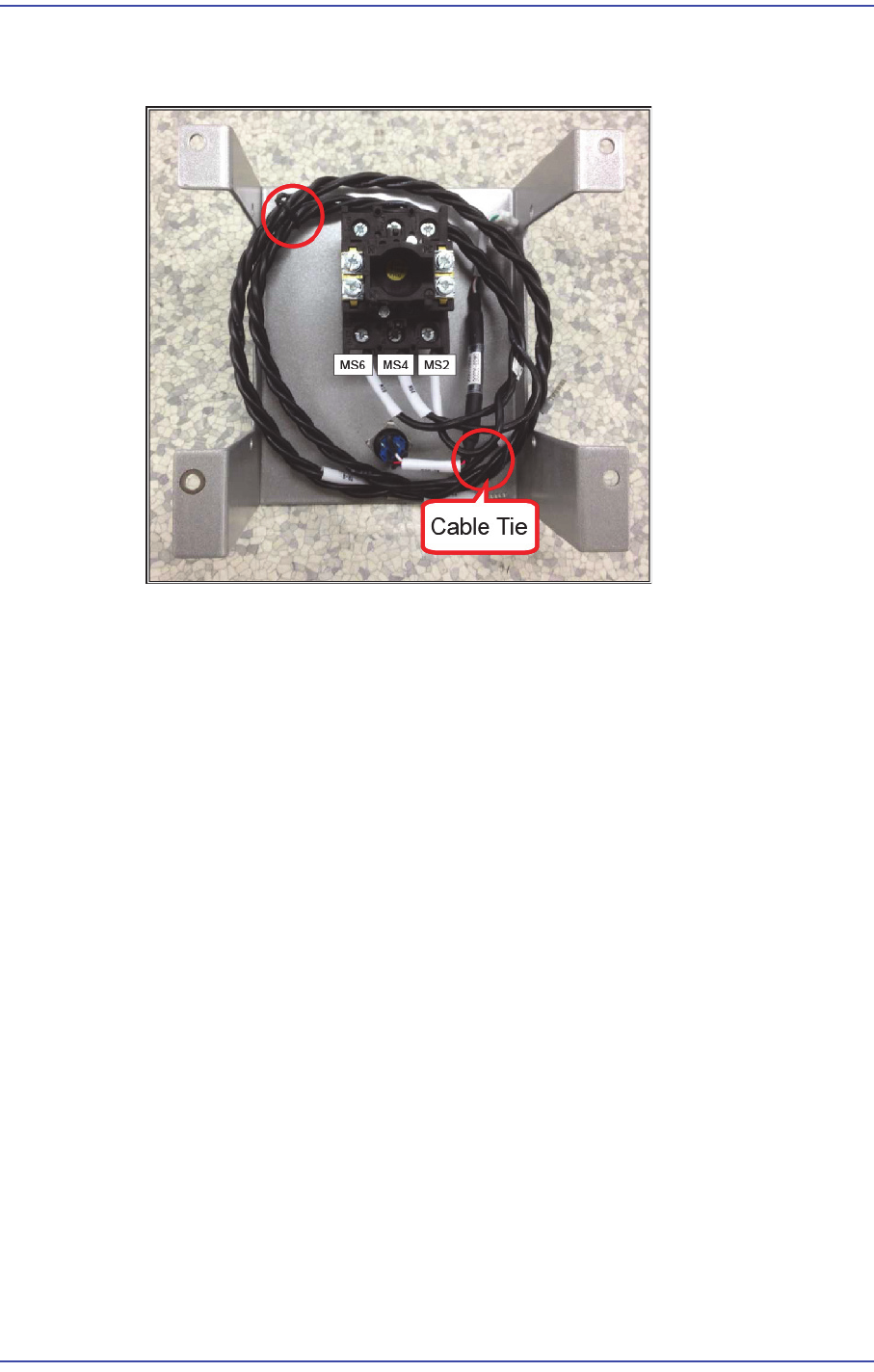
4) After connecting the connector as shown in the following figure, arrange the cables
using cable ties.
15-14
Fast & Flexible Chip Shooter DECAN F2 Service Manual
15.6. Rear Power Panel
15.6.1. Required Tools
Crosshead (Phillips) screwdriver and flathead screwdriver
T Wrench or Hex Wrench
15.6.2. Part list of Rear Power Panel
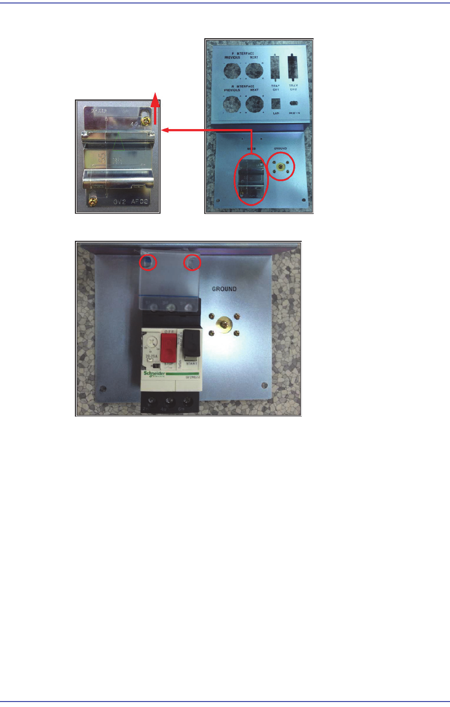
15.6.3. Rear Power Panel assembly method
Warning If the main circuit breaker located at the lower left on the
rear side of the machine is not turned off before performing
service, serious injury may occur. Perform servicing with the
power supply to the motor cut off without fail.
No Part No. Part Name Unit
Quantity
1 FC09-003402A BRACKET-REAR ELEC
PANEL
1
2 J3716070A
PANEL 취부대
GV2-AF02 1
3 J7152027A GROUND TERMINAL
J7152027A
1
4 J36031004A MAIN_CIRCUIT_BREAKE
R
GV2ME22 1
5
J72521004A ELEC_ACRYL J72521004A
1
6
AM03-003542A CABLE ASSY-INLINE_IN-
OUT
SM421_CV10
6-2
1
7
AM03-010846A CABLE ASSY-
INLINE_NEXT_PRE
SM511_CV10
7-1
1
8
J3713061A CONNECTOR 555376-1
1
9
AM03-010987A CABLE ASSY-LAN_EXT SM511_VM11
1-1
1
10
AM03-010913A CABLE ASSY-
REAR_ELEC_PANEL_EA
RTH
SM511_PW0
03-1
1
15-15
Electric Device
1) Assemble the ground terminal and panel attachment rack to the panel.
2) Assemble the MCCB and its acrylic cover to the rear panel.
3) Assemble the Safeguard Override Key to the panel using a switch assembling jig.