DECAN_F2_Service(Eng_Ver1).pdf - 第579页
18-59 Machine Calibration <Start> button Start the Mapping. <T est> button Perform test for the mapping result. The light level that does not satisfy the reference value is searched automatically and it i…
18-58
Fast & Flexible Chip Shooter DECAN F2 Service Manual
CIRCLE: Refers to the round area.
RECT: Refers to the rectangular area.
NONE: Area not designated
<2. Camera> group
Selects the camera for performing lighting brightness test or mapping. Activated
cameras can be designated at the same time.
<3. Tool Setting> group
Performs test or preparation for mapping.
<Prepare Test /Mapping> button
Return all nozzles mounted on the head to each corresponding ANC hole.
Before doing so, arrange the LightFly nozzle, a nozzle for calibration into the
No. 1 hole of the ANC.
If the nozzle arrangement is finished, the <Start> button and <Test> button in
the <Mapping>group.
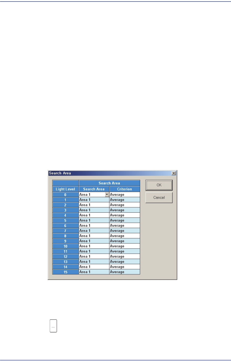
<4. Search Area> group
Clicking the button corresponding to the light for which mapping is to be
performed will display the following dialog box.
Click on the button corresponding to the illumination for mapping, set the test area
(Area 1 ~ 4) to 16 illumination levels for each lighting, and setup the average
illumination level for each pixel of the test area to the maximum value.
<Mapping> group
button
Select the Map File to be used for mapping. Since the file name is set
automatically, do not change it.

18-59
Machine Calibration
<Start> button
Start the Mapping.
<Test> button
Perform test for the mapping result. The light level that does not satisfy the
reference value is searched automatically and it is displayed in the result file.
Perform mapping with the <Refine Mapping Result> check box being selected.
State display
Displays current progressing state.
Camera (Number of camera for which test or maping is completed) /(Total number
of selected camera)
(I: Inner Level, O: Outer Level, S: Side Level, B: Back Level)
<Close> button
Closes the dialog box.
<Update> button
Transmits the set data to the equipment and closes the dialog box.
<Cancel> button
Ignores the set data and closes the dialog box.
18-60
Fast & Flexible Chip Shooter DECAN F2 Service Manual
18.3.10.4. Head Offset Calibration
Measure the distance (XY Offset) between the center of the gantry fiducial camera and the
center of each head.
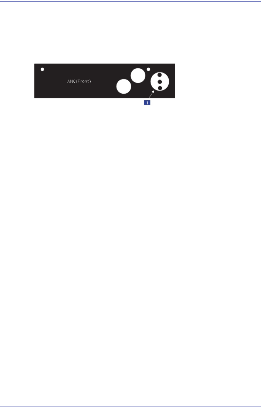
In order to perform calibration of the XY offset of each head, first check if the calibration
tool is placed on the calibration tool position of the front ANC.
1: Calibration Tool Position
The following is the procedure to calibrate the XY offset of the head;
1. Click the <Nozzle Prepare> button and insert the CN400 nozzle into the No. 1 hole of
the ANC manually.
2. If the <9. Head Offset> is clicked after selecting the <Automatic Next> check box,
calibration is performed for the selected gantry automatically.
If calibration is performed after selecting the <No Real Motion [Manual]> check box,
the nozzle is inserted into each head manually. Click the <Next> button to move onto
the next step.
If calibration is performed without selecting either the <Automatic Next> check box
or < No Real Motion [Manual]> check box, the nozzle is changed automatically for
the currently selected nozzle. Click the <Next> button to move onto the next step.
If the <9. Head Offset> button is clicked, the message “First, We must Put all Nozzles
From Heads Manually. To Moving Down Z Axis, Click [Next]” appears in the
message box. Click the <Next> button to move down the Z axis of the head in order to
remove all nozzles inserted in the nozzle-holder manually.