DECAN_F2_Service(Eng_Ver1).pdf - 第361页
14-21 Board 14.4. Feeder Base Board 14.4.1. Required Tools Crosshead (Phillips) screwdriv er and flathead screwdriver T W rench or Hex W rench Nipper (Remove the Cable Tie) 14.4.2. Feeder Base Boar d Replacement Pr…

14-20
Fast & Flexible Chip Shooter DECAN F2 Service Manual
Ref The part number of the new Board is J91741337A.
14-21
Board
14.4. Feeder Base Board
14.4.1. Required Tools
Crosshead (Phillips) screwdriver and flathead screwdriver
T Wrench or Hex Wrench
Nipper (Remove the Cable Tie)
14.4.2. Feeder Base Board Replacement Procedure
1) Close the PC as usual and turn off the main switch at the front of the machine.
2) Turn off the main power supply to the machine.
Warning Before servicing the machine, turn off the power switch
located at the front bottom as well as the main circuit
breaker at the rear bottom of the machine. Otherwise,
serious personal injury may occur. Perform servicing with
the power supply to the machine cut off without fail.
Warning Be sure to wear anti-electrostatic gloves when servicing the
machine.
14-22
Fast & Flexible Chip Shooter DECAN F2 Service Manual
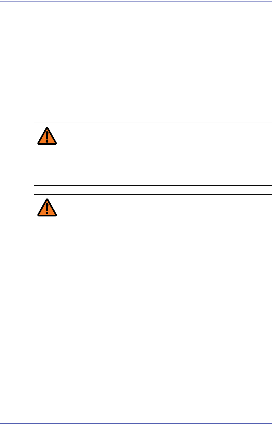
3) Unscrew the fixing bolts(16-M3*8) securing the Feeder Base Board Cover using a
wrench and remove it.
4) Remove the cable connected to the board.
5) Remove the Board.
6) Assemble in the Feeder Base a new Board.
Ref The Left, Right part number of the new Board is AM03-000694A /
AM03-000693A.
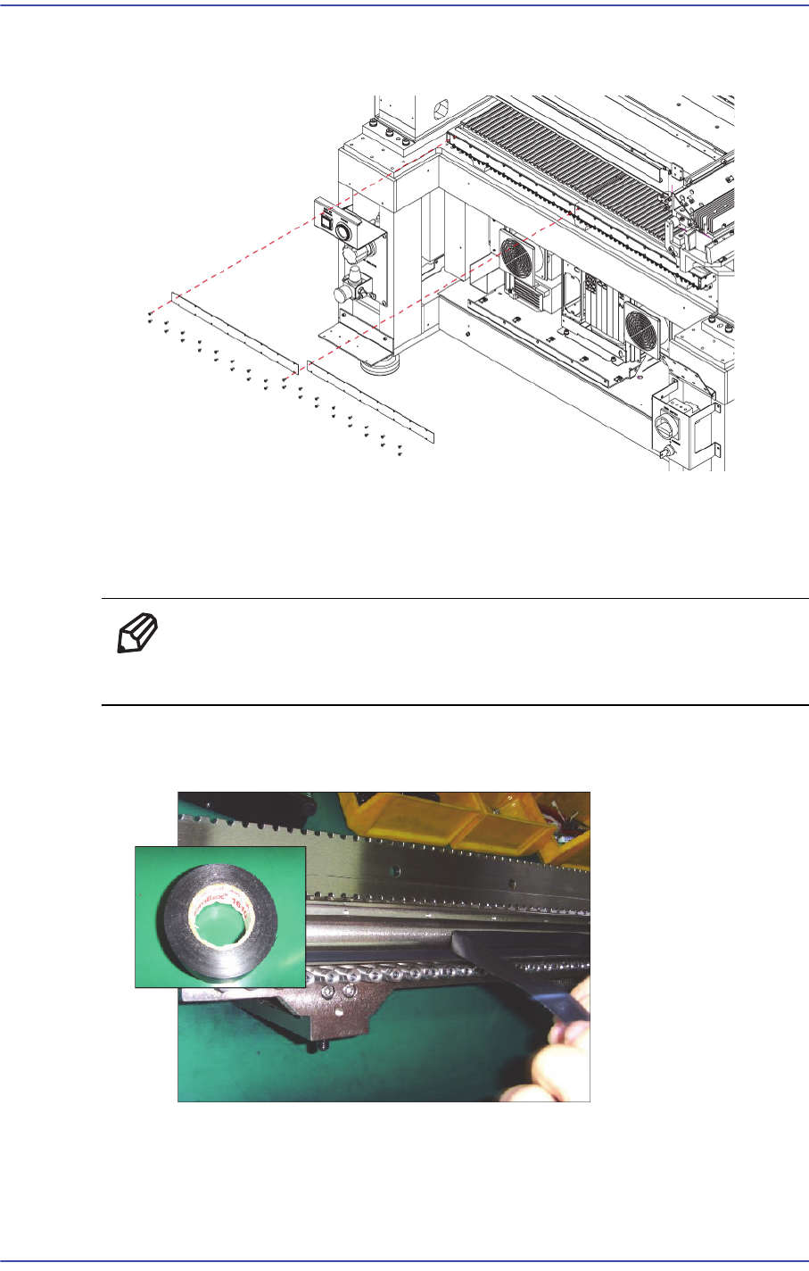
7) When assembling a board, attach the electrical tape to the area where it comes into
contact with the feeder base body.
8) After attaching the PCB board, perform a test using the feeder index tester.