DECAN_F2_Service(Eng_Ver1).pdf - 第223页
10-9 Y-Axis Frame Check the program is exited normally . For the setup method using the ABS S T700 Signal Adjustment Program, refer to the following procedure. (When the COM port has been conn ected properly , the &q…
10-8
Fast & Flexible Chip Shooter DECAN F2 Service Manual
Connect the USB connection cable to the laptop computer and machine and check
the set port values. (Click Computer Properties > Hardware > Device Manager >
Port (COM & LPT) to check the values.)
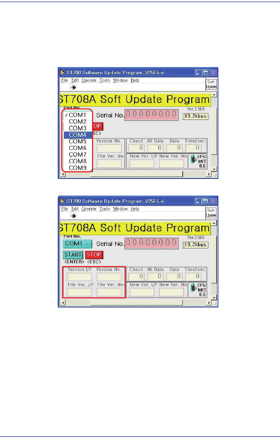
Run the ST708A Software Upgrade Program.
Input the confirmed COM Port.
Press F5 button to check the current version.
Click ‘Start’ when the version needs to be upgraded.
10-9
Y-Axis Frame
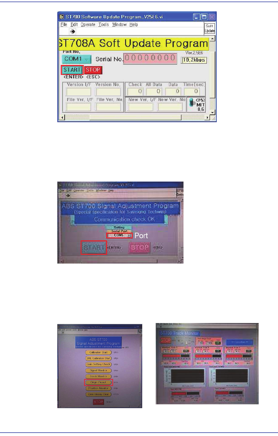
Check the program is exited normally.
For the setup method using the ABS ST700 Signal Adjustment Program, refer to
the following procedure.
(When the COM port has been connected properly, the "Communication Check
OK" message is generated.)
Click the ‘Origin Preset’ button to check whether the read values of A, B and C
phases as well as MED-FINE and COAMED values fall within the specified
range.
(Specified value of A, B and C phases: - MIN ~ MAX : Within 50~90)
(MED-FINE, COA-MED - MIN ~ MAX : Within -0.4~0.4)
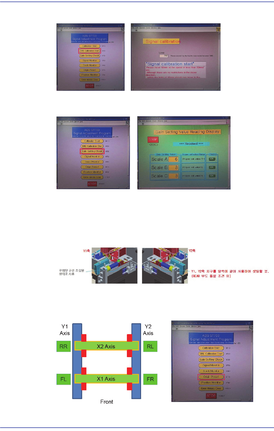
Click the ‘Set Calibration’ button to perform calibration.
10-10
Fast & Flexible Chip Shooter DECAN F2 Service Manual
(The Y-axis moves to the front once and then to the rear once again.)
Click the ‘Gain Setting Check’ button to perform setup so that the scale values of
the A, B and C phases fall within the specified range.
Click the ‘Origin Preset’ button to check again whether the read values of A, B
and C phases as well as MED-FINE and COAMED values fall within the
specified range.
To calibrate the Y-axis, as shown in the figure, in close contact with Jig O points
(Origin) to the Setting.
After setting the origin of the X and Y axes (Jig in a state close to the axis), click
the ‘Position Monitor’ to check whether the FL RR is -55mm±1.0mm and FR RL
is +55mm ±1.0mm.