DECAN_F2_Service(Eng_Ver1).pdf - 第97页
4-9 X Frame 4.3. Sensor 4.3.1. Required Tools T wrench (other tools supplied) or hex wrench Gear wrench or torque wrenc h 4.3.2. Position of Sensor 4.3.3. Sensor Repl acement Procedure 1) Manipulate t he teaching box…
4-8
Fast & Flexible Chip Shooter DECAN F2 Service Manual
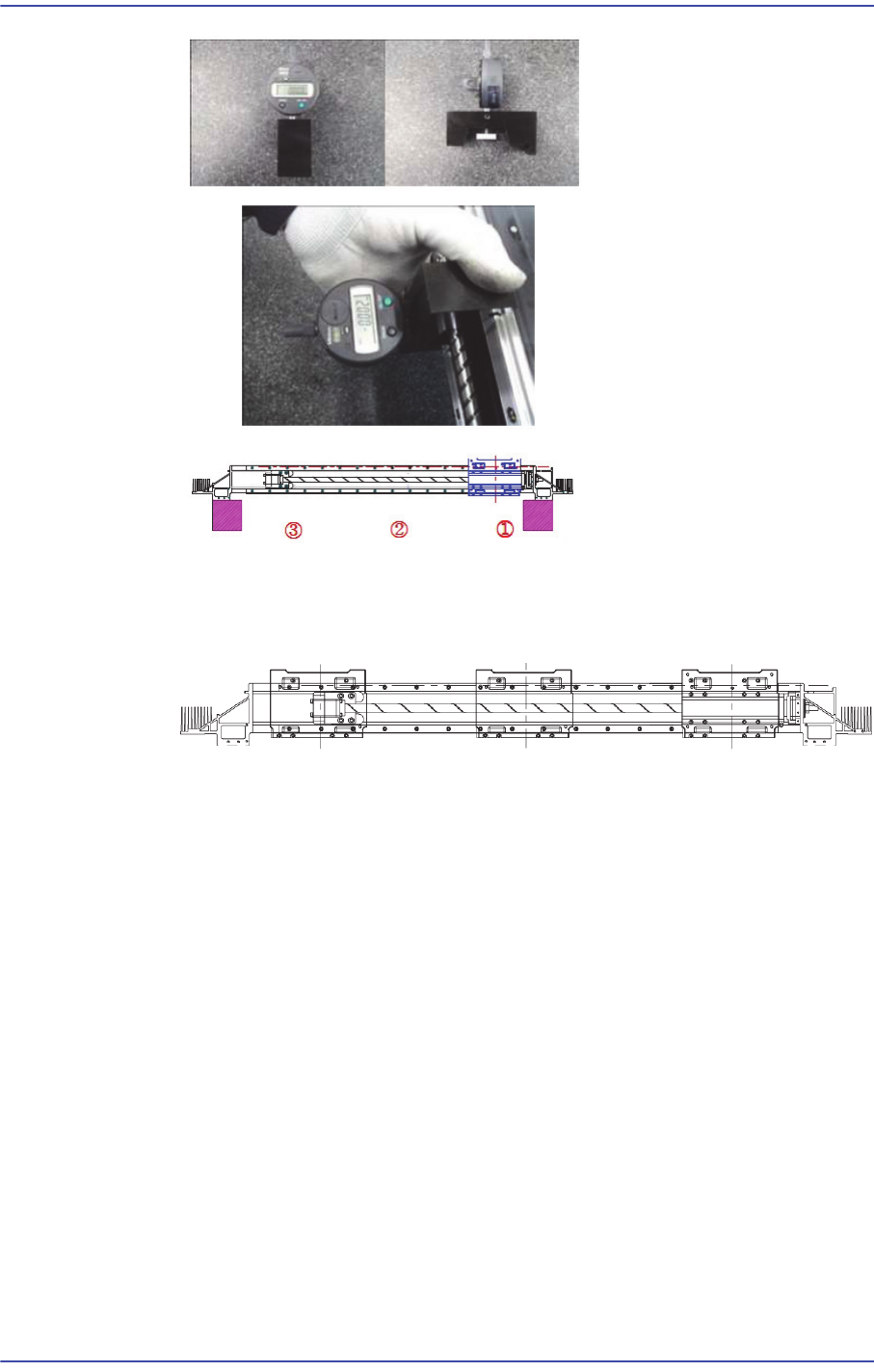
Please measure the concentricity of Ball Screw after assembly.
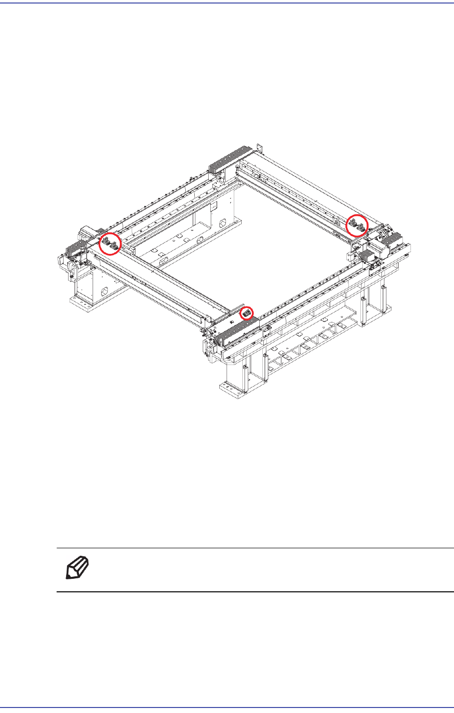
When assembling the Base Head Carrier, please assemble it using Jig at three points
left, right, in the middle as shown in the following figure.
10) Turn on the main switch on the front side of the machine and boot the PC once the
assembling is completed.
11) Perform the following calibrations.
Axis Home Calibration
Common X-Y (1'st)
Thermal Mapping
Gantry Mapping
ANC, Position Teaching
Total Time : 0.8Hour
4-9
X Frame
4.3. Sensor
4.3.1. Required Tools
T wrench (other tools supplied) or hex wrench
Gear wrench or torque wrench
4.3.2. Position of Sensor
4.3.3. Sensor Replacement Procedure
1) Manipulate the teaching box to move the X Frame to the front.
2) Close the PC as usual and turn off the main switch at the front of the machine.
3) Disconnect the sensor cable connector.
4) Unscrew the fixing bolts securing the Sensor and remove sensor.
5) Replace the Sensor with a new one.
Ref The part number of the new Sensor is J3212022A.
6) Perform the following calibrations.
Axis Home Calibration
Common X-Y (1'st)
Thermal Mapping

4-10
Fast & Flexible Chip Shooter DECAN F2 Service Manual
Gantry Mapping
ANC, Position Teaching
Total Time: 0.8Hour