DECAN_F2_Service(Eng_Ver1).pdf - 第139页
5-39 Head 5.9.3.1. How to check the Z phase of the head motor 1) Move the corresp onding axis block con nected to the head AM P down. 2) When the physical Z phase of the motor is detected during the above process, the SV…
5-38
Fast & Flexible Chip Shooter DECAN F2 Service Manual
Ref The part number of the new motor is J31081047A.
8) When assembling, refer to the following.
Belt Tension : 136~175Hz
Measurement Position :
9) Once the assembling is completed, turn on the main switch on the front of the machine
and boot the PC.
5-39
Head
5.9.3.1. How to check the Z phase of the head motor
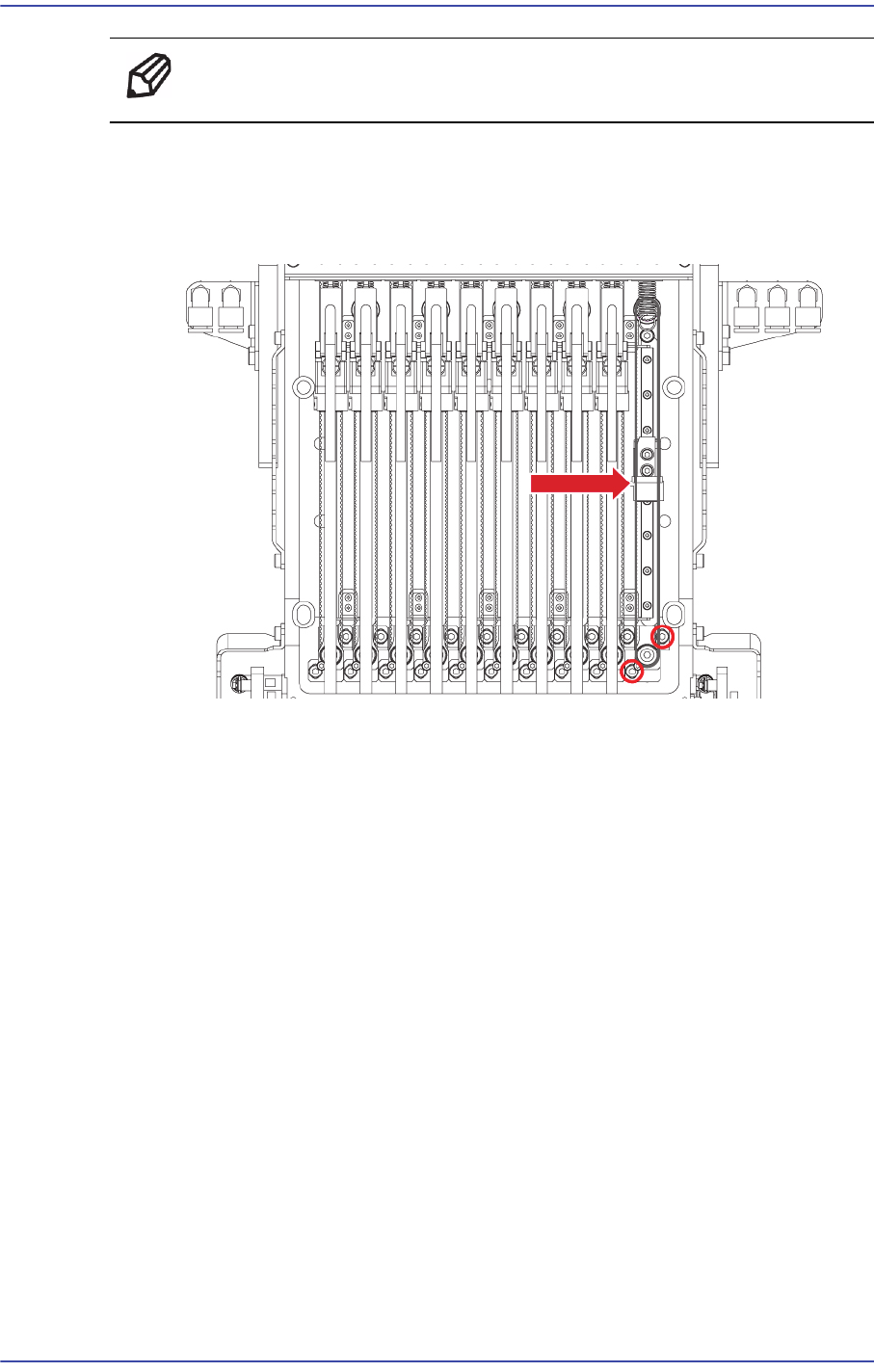
1) Move the corresponding axis block connected to the head AMP down.
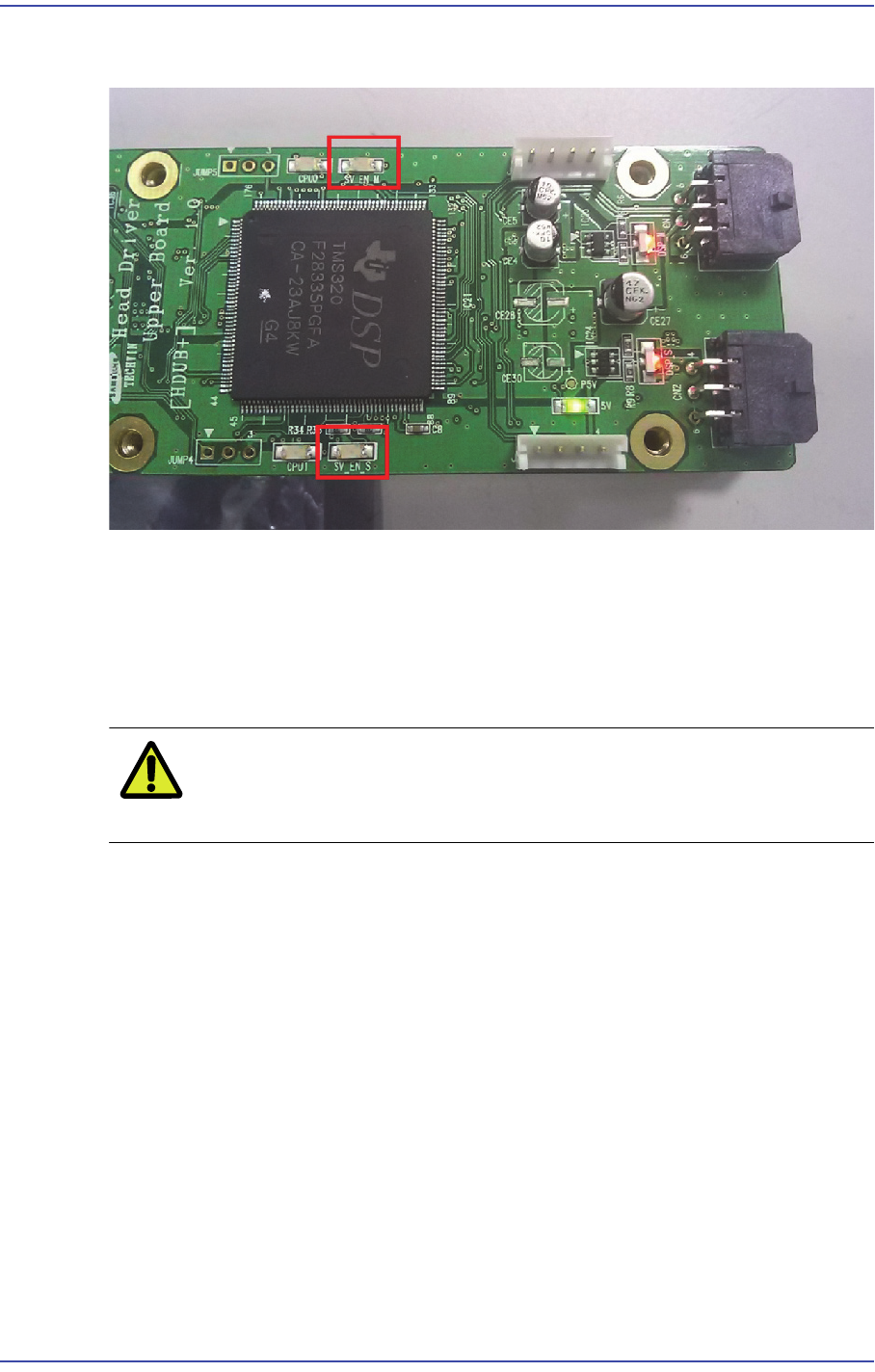
2) When the physical Z phase of the motor is detected during the above process, the
SV_EN LED is turned on.
3) That is, the position at which the SV_EN_LED is turned on is the Z phase of the
corresponding axis motor.
Caution Since the range of the physical Z phase is small, move the
axis block as slowly as possible.
5-40
Fast & Flexible Chip Shooter DECAN F2 Service Manual
5.9.3.2. Alarm Code and Parameter Download Procedure
1) When checking the New Dual Head AMP Alarm and downloading the parameter, RS-
232C is used. Therefore, in order to check the alarm of the corresponding AMP, check
the setup of the serial port.
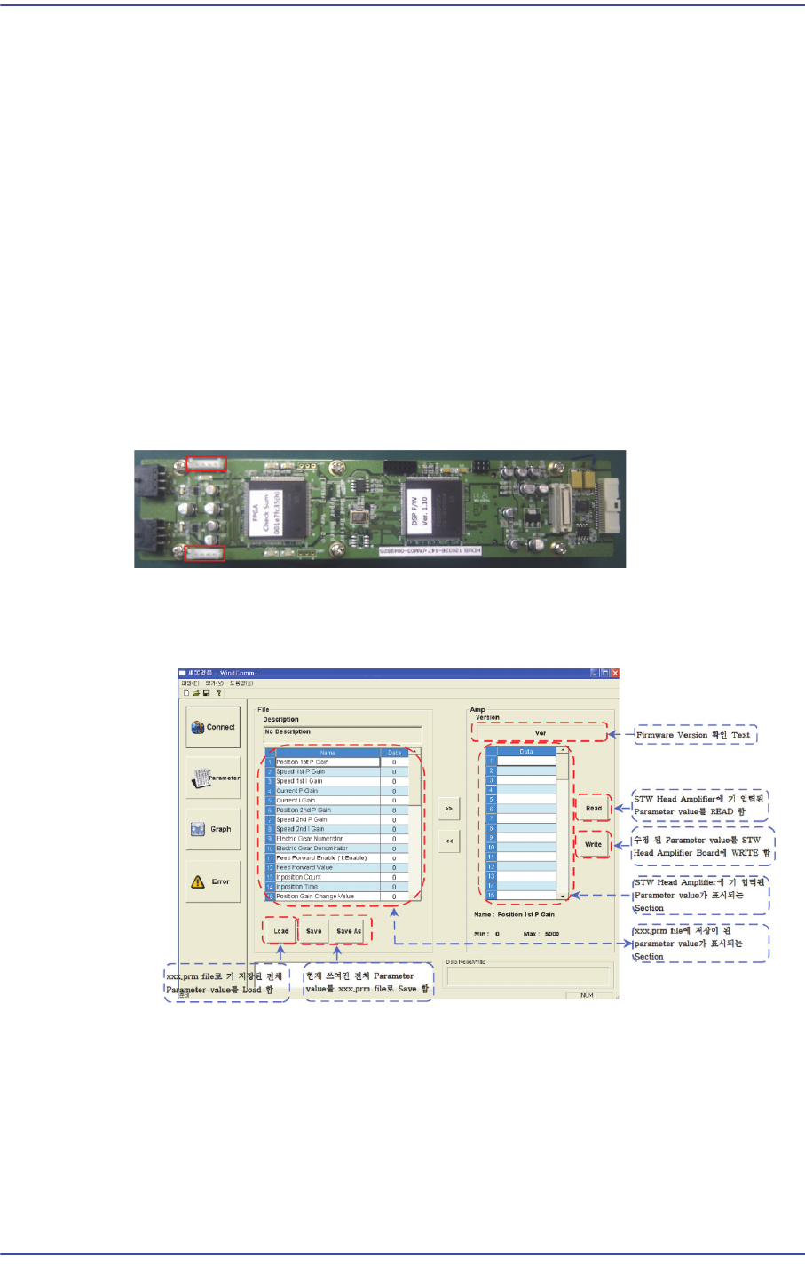
2) When checking the New Dual Head AMP Alarm and downloading the parameter, the
dedicated MMI program, WindComm+, must be used.
3) The WindComm+ MMI consists of four sections.
In order to check the alarm, use the ‘Alarm’ section of the MMI.
In order to download the parameter, use the ‘Parameter’ section of the MMI.
4) In order to check the parameter and alarm, connect the RS-232 cable to the new Dual
Head AMP connector.
5) Check the alarm by connecting the RS-232 cable to the connector in the direction in
which the red LED is turned on.
6) The MMI WindComm+ Parameter download screen is dedicated for the new dual
head amp and its download procedure is as follows: