DECAN_F2_Service(Eng_Ver1).pdf - 第68页
3-6 Fast & Flexible Chip Shooter DECAN F2 Service Manual Caution If the level of the mach ine is not adjusted, i t has influence on the accuracy of the machine. Be sure to level the machine and check if the feet o f …
3-5
Installation & Operation
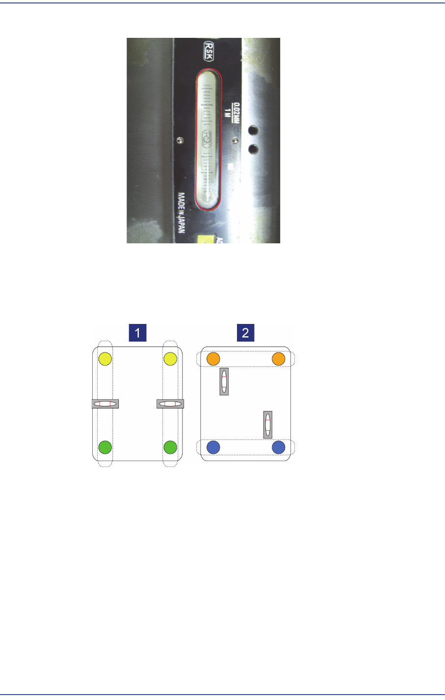
2: Y Axis Leveler
4) When adjusting the level of the foot, it is recommended to group 2 feet as one set and
adjust the level in each direction. (At this time, adjust the foot finally.)
Leveling in the front-rear direction: Adjust feet at the front and rear in pair
Leveling in the left-right direction: Adjust feet at the left and right in pair
5) The feet of the machine must be supported at uniform force, which is adjusted by
tightening the lock nut of the foot so that uniform force is applied to the feet. Check if
there is any loose foot. Tighten the lock nuts for 4 legs after leveling is finished.
3-6
Fast & Flexible Chip Shooter DECAN F2 Service Manual
Caution If the level of the machine is not adjusted, it has influence
on the accuracy of the machine. Be sure to level the
machine and check if the feet of the machine are tightened
properly.
There must be no grease on the lock nut and foot nut. If
there is grease on them, clean it completely. Otherwise, the
nut is loosened during machine operation, which may
damage the machine.
6) Install the machine that was move to the designated place after confirming the place of
the installed line from the responsible personnel of the customer.
7) Remove the vinyl sheet, internal packing material and desiccant.
Caution If the machine is unpacked by imposing excessive impact
on it, the machine cover may be damaged. Do not unpack
the machine by imposing excessive impact on it.
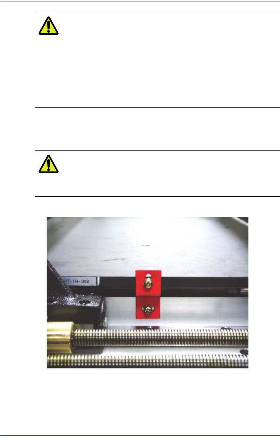
8) Remove the BUT fixing bracket.
3-7
Installation & Operation
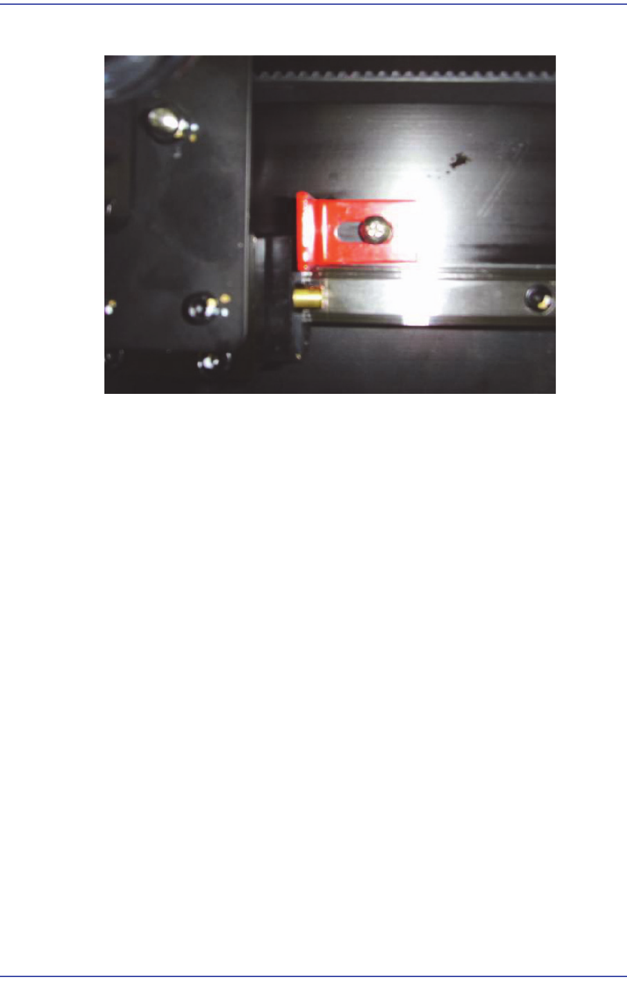
9) Remove the Shuttle fixing bracket.
3.1.4. Installation of Parts
3.1.4.1. Required Tools
T wrench (other tools supplied) or hex wrench
Gear wrench or torque wrench
Crosshead (Phillips) screwdriver and flathead screwdriver
3.1.4.2. Part List
Signal Light
Mouse, Mouse Pad
Keyboard
Monitor Bracket, Monitor
3.1.4.3. Part Installation Procedure
1) Connect the connector at the center inside the machine and signal light connector and
secure the signal light at the center on the upper surface with fixing bolts.