DECAN_F2_Service(Eng_Ver1).pdf - 第424页
17-12 Fast & Flexible Chip Shooter DECAN F2 Service Manual [Measures] Perform HDD recovery and reinstall the MMI. Remove the SBC board from the vision boar d connec tor and insert it again. Then remove the vision…

17-11
Troubleshooting
Replace the Base Control board and check whether the same problem occurs
Check whether the output voltage (24V) of the PC power supply is normal
Replace the back plane board and check whether the same problem occurs
Replace the vision board and check whether the same problem occurs
[Measures]
Replace the CPU cooling fan and SBC board.
Remove the SBC board from the vision board and then insert it again. Remove the
vision, NCIO and ZMP boards from the back plane board slot. Then insert it again
properly.
Check whether a bad sector has occurred through HDD inspection. If it has no
problem, reinstall the MMI.
Replace Base Control board.
Replace the power supply unit
Replace the back plane board.
Replace the vision board.
E0605 An MFC related arithmetic operation error occurred while booting the MMI (system
file not found)
[Cause]
A problem occurred to the MMI or Windows O/S
[How to Check]
Perform HDD recovery and reinstall the MMI. Then check whether the same problem
occurs
[Measures]
Perform HDD recovery and reinstall the MMI.
E0606 Defective MMI booting (assert failure occurred)
[Cause]
The Windows system file is damaged
The SBC board is not properly connected to the vision board connector or the vision
board is not properly inserted into the back plane slot (defective SBC board contact)
[How to Check]
Perform HDD recovery and reinstall the MMI. Then check whether the same problem
occurs
Remove the SBC board from the vision board connector and insert it again. Then
remove the vision board from the back plane board slot and insert it again properly and
then check whether the same problem occurs

17-12
Fast & Flexible Chip Shooter DECAN F2 Service Manual
[Measures]
Perform HDD recovery and reinstall the MMI.
Remove the SBC board from the vision board connector and insert it again. Then
remove the vision board from the back plane board slot and insert it again properly.
E0607 Windows system error occurred while loading the MMI (forced exit)
[Cause]
The Windows system file is damaged
The SBC board is not properly connected to the vision board connector or the vision
board is not properly inserted into the back plane slot (defective SBC board contact)
[How to Check]
Perform HDD recovery and reinstall the MMI. Then check whether the same problem
occurs
Remove the SBC board from the vision board connector and insert it again. Then
remove the vision board from the back plane board slot and insert it again properly and
then check whether the same problem occurs continuously
[Measures]
Perform HDD recovery and reinstall the MMI.
Remove the SBC board from the vision board connector and insert it again. Then
remove the vision board from the back plane board slot and insert it again properly.
17-13
Troubleshooting
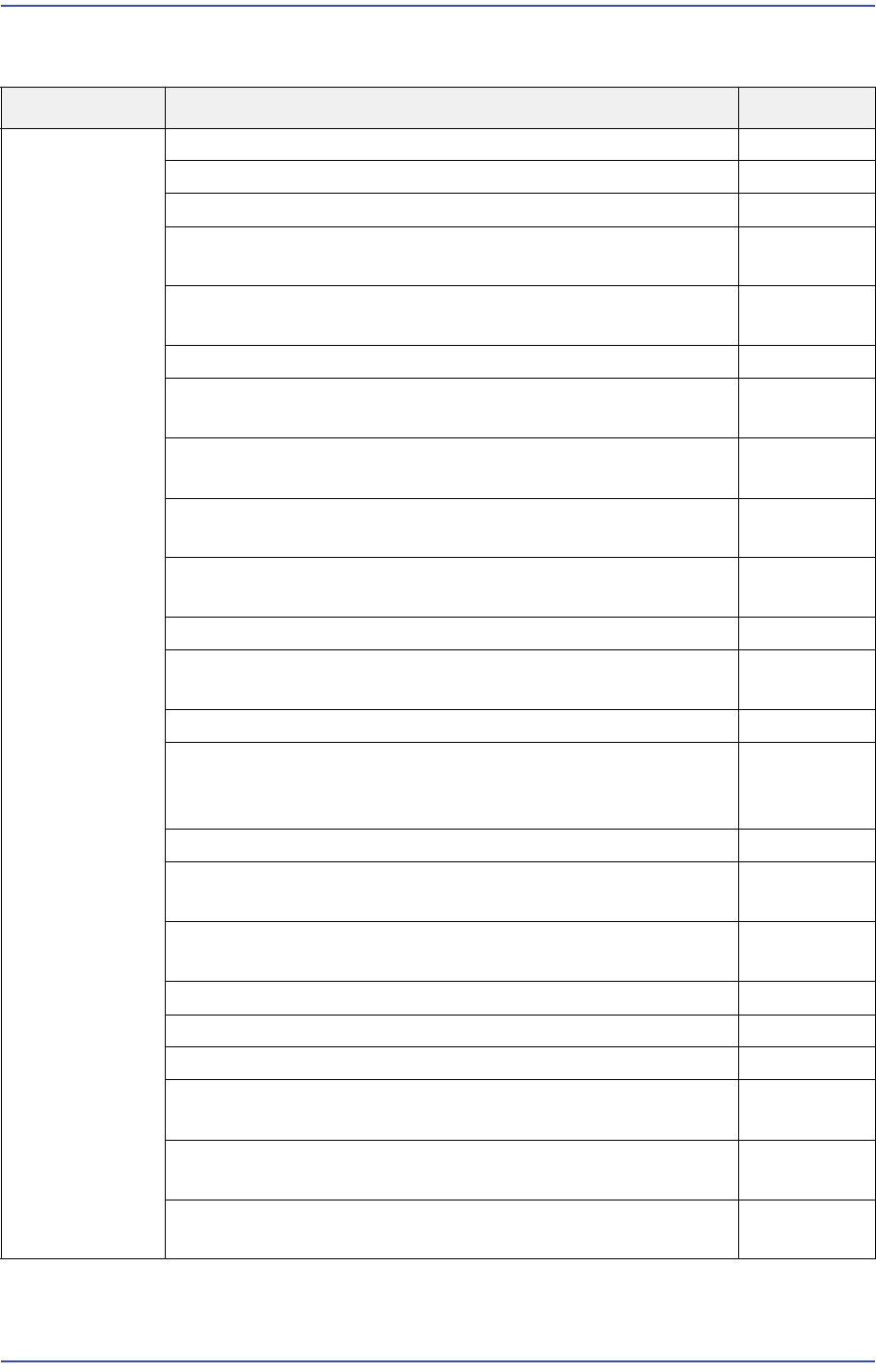
17.3.3. SW Error, etc. While Executing the MMI
Cause Description Remarks
SW Error Pause while downloading the MMI E7000
Ram Ring Error E7001
The Assert error occurred while loading the PCB program E7002
Assert[O] error occurred (File. Common.MmiRT Comm.
DPRAM -.Struct.h Line 145)
E7003
The monitor image is turned off intermittently and discolored,
and the screen vibrates
E7004
The optimizer is shut down while running it E7005
An error occurred when executing a command from the
optimizer
E7006
An error occurred when downloading a PCB file after running
the optimizer
E7007
An error occurs where the size of a certain part exceeds the
FOV when running the optimizer
E7008
When running the optimizer, the Download Manager Mode is
disabled
E7009
After running the optimizer, exit the MMI by force E700A
An error occurred when running the optimizer after importing
the Txt file
E700B
Optimizer Error E700D
An error occurred that the front gantry fiducial camera
recognized the fiducial mark of the PCB transferred to the
work station of the rear lane
E700E
Exceeded the bad mark recognition range E700F
The fiducial mark recognition position of the front PCB is
different from that of the rear PCB
E7010
The confirmation window was not displayed when the
fiducial mark recognition error occurred
E7011
Failed to recognize the second PCB fiducial mark E7012
An error occurred when using an array fiducial E7013
The DLL file cannot be found while executing the MMI E7014
When opening a file, even though the file name exists, the
file is not opened
E7015
When opening the PCB file, the PCB file in a certain folder
was not opened
E7016
The buzzer sounds continuously with the MMI being closed
after a message was generated during operation
E7017