DECAN_F2_Service(Eng_Ver1).pdf - 第390页
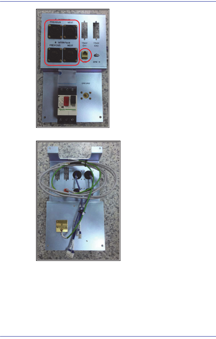
15-16 Fast & Flexible Chip Shooter DECAN F2 Service Manual 4) Assemble the LAN EXT cable and EAR TH cable to the rear panel.
15-15
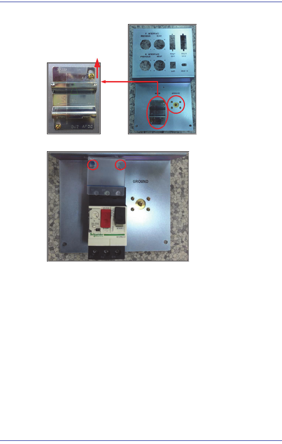
Electric Device
1) Assemble the ground terminal and panel attachment rack to the panel.
2) Assemble the MCCB and its acrylic cover to the rear panel.
3) Assemble the Safeguard Override Key to the panel using a switch assembling jig.
15-16
Fast & Flexible Chip Shooter DECAN F2 Service Manual
4) Assemble the LAN EXT cable and EARTH cable to the rear panel.
15-17
Electric Device
15.7. UPS
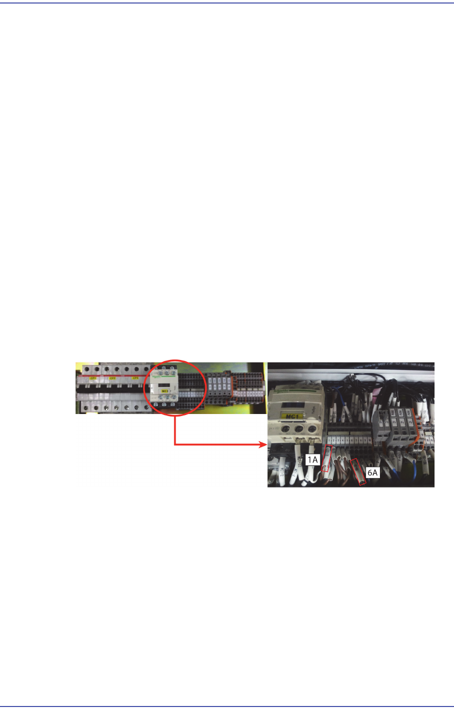
15.7.1. How to connect the Cable
1) Open the back cover, remove the Cable attached 1A Power Distribution Terminal
Block, in 6A, to connect with the Cable Inlet.
(Connect to the terminal of Knowle use or soldering)
1A => Inlet for AC terminal (Hot)
6A => Inlet terminal for AC (Neutron)
After the connection is handled properly by using the shrinkable tube and an insulating
tape attached portion is not exposed.
2) (Yellow / Green and General Green) ground wire Inlet Cable is bitten by a ground
Plate of equipment by extending.
3) 1A of the Terminal Block, the bite to the tip of the 6A Outlet Cable.
Outlet for AC terminal (Hot) => 1A, Outlet for AC terminal (Neutron) => 6A
4) Once these steps have been completed, connect each to the UPS Outlet Cable and Inlet
Cable, to increase the power of the device.
(Single-stranded two + ground wire power line) 3 layer is described tip: Inlet
Cable.
Outlet Cable: (2 the power supply line) two, tip nose plug shape of pig.